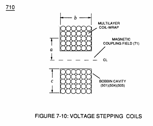
Figure (7-10)
Voltage Stepping Coils
How it is written
- (7-10) 10×
Drawings 5
-
(710) of Figure (7-10) · Inductance (FL)
-
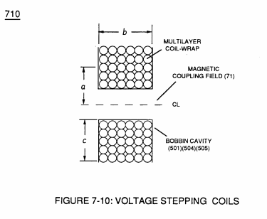
(710) of Figure (7-10) · Capacitance (Cd)
-
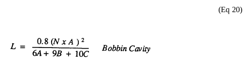
... each bobbin cavity adhering to equation (Eq 20), as illustrated in (710) of Figure (7-10). · Transformer Action
-
(710) of Figure (7-10) · Transformer Action
-
Captioned as this figure · WFC 426 - Illustrations
On this figure 7
- 52 Secondary Coil
- 505 Secondary Coil-cavities
- 612 Dynamic Electrical Charging Effect
- 618 Blocking Diode
- 640 Self-Inductance
- 710 Voltage Stepping Coil
- FL Optimize The Electromagnetic Field Strength
Where it is named · 10
Inductance (FL) 2×
-
(710) of Figure (7-10)
Capacitance (Cd) 2×
-
Inductor (614) and Inductor (615) of Figure (7-1) as to (670) of Figure (7-6) is wound or coil-wrapped (see multi-layer equation Eq. 20) in such a manner as to increase the magnetic flux intensity (D1a xxx D1n) of Figure (7-3) as to (580) as to Figure (6-1) in reference to (710) of Figure (7-10) between the turns (618a xxx 618n) of coil-wrap (640).
-
(710) of Figure (7-10)
Multi-layer Coil 2×
-
(710) of Figure (7-10)
Transformer Action 4×
-
(Ns) is the number of turns of wire for each bobbin cavity (505) of Figure (6-1) as to (710) of Figure (7-10) that are electrically connected in series arrangement (505a xxx 505n) to form Secondary Coil-Wrap (52),
-
(710) of Figure (7-10)
-
... each bobbin cavity adhering to equation (Eq 20), as illustrated in (710) of Figure (7-10).
-
(710) of Figure (7-10)