(140)
Resonant Capacitor
Also written Resonant Cavity · Gas Resonant Cavity · Furnace Nozzle Assembly · Resonant Cavities
Where it is first named
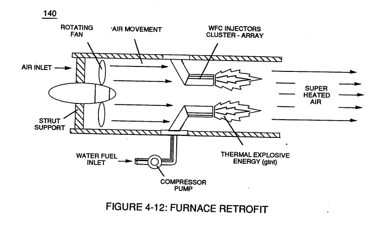
In terms of mechanical interfacing: Water Fuel Injector Assembly (10) of Figure (4-1) can replace standard fuel-injector ports of existing jet engines as shown in (150) of Figure (4-13); or be utilized in Furnace Nozzle Assembly (140) of Figure (4-12) for grain dryers or conventional\heating systems;
How it is written
- (140 -170) 5× with (170) Resonant Cavity
- (140) 3×
- (140 - 170) 1× with (170) Resonant Cavity
Drawings 67
-
Figure (3-6) · Voltage Amplitude Control Circuit (50)
-
Figure (3-6) · Cell Driver Circuit (90)
-
reciprocating WFC Fuel-kits can be similar to Car design (340); · Aviation Application
-
Carries this number · WFC 422DA - Illustrations
-
(650) of Figure (7-4) · Amp Inhibiting Circuit Vs Voltage Enhancement
-
Carries this number · Steam Resonator Assembly
-
Carries this number · Steam Resonator Assembly
-
Figure (3-6) · Water Fuel Injection System - Page 1
-
Figure (4-12) · Water Fuel Injection System - Page 3
-
Carries this number · VIC Matrix Circuit
-
(T2) of Figure (7-8) · Instant Explosion of Water
-
Figure (7-8) · Resistance (Rs)
-
(650) of Figure (7-4) · Resistance (Rs)
-
(690) of Figure (7-8) · Resistance (Rs)
-
(630) of Figure (7-2) · Inductance (FL)
-
Carries this number · Inductance (FL)
-
(670) of Figure (7-6) · Inductance (FL)
-
(690) of Figure (7-8) · Inductance (FL)
-
LC circuit of Figure (7-2) · Inductance (FL)
-
(650) of Figure (7-4) · Inductance (FL)
-
(650) of Figure (7-4) · Capacitance (Cd)
-
(670) of Figure (7-6) · Capacitance (Cd)
-
(670) of Figure (7-6) · Capacitance (Cd)
-
(690) of Figure (7-8) · Capacitance (Cd)
-
(690) of Figure (7-8) · Inductance Reactance (Rs - Cd - FL)
-
Figure (7-8) · Inductance Reactance (Rs - Cd - FL)
-
Carries this number · Taper Resonant Capacitor (ERt)
-
(690) of Figure (7-8) · Taper Resonant Capacitor (ERt)
-
Resonant Capacitor (140 -170) of Figure (7-6) · Capacitance Reactance
-
Capacitor (ER) of Figure (7-2) · Capacitance Reactance
-
"Voltage Deflection" of Figure (7-4) · Capacitance Reactance
-
690 of Figure 7-8 · Circuit Resistance
-
Resonant Voltage Effect (670) of Figure (7-6) · Transformer Action
-
Opposite Electrical Attraction Force (SS' ~ 617 ~ RR' - T3 - SS' ~ 617 - RR') of Figure (7-4) · Electron Bounce Phenomenon
-
(52) of Figure (7-8) · Electron Bounce Phenomenon
-
Carries this number · WFC 426 - Illustrations
-
Carries this number · WFC 426 - Illustrations
-
Carries this number · WFC 426 - Illustrations
-
Carries this number · 8-2 - Traveling Voltage Wave-Guides
-
(690) of Figure (7-8) · 8-2 - Traveling Voltage Wave-Guides
-
(52) of Figure (7-8) · 8-3 - Electrical Voltage-Pulse Wave-Transmission
-
(Cp) of Figure (7-8) · 8-4 - State Space (Sp)
-
(650) of Figure (7-4) · 8-4 - State Space (Sp)
-
(690) of Figure (7-8) · 8-6 - VIC Voltage Sync-Pulse Circuit
-
(650) of Figure (7-4) · 8-6 - VIC Voltage Sync-Pulse Circuit
-
(Cp) of (7-8) · 8-6 - VIC Voltage Sync-Pulse Circuit
-
Carries this number · WFC Development Objectives
-
(690) of Figure (7-8) · Propagating Electrical Stress
-
Carries this number · Propagating Electrical Stress
-
The figure it sits on · Electronic Circuit Design
-
Voltage Intensifier Circuit (620) of Figure (7-1) · Instant Explosion of Water
-
(628) of Figure (7-7) · Instant Explosion of Water
-
(620) of Figure (7-1) · Instant Explosion of Water
-
(620) of Figure (7-1) · Resistance (Rs)
-
(614) of Figure (7-1) · Inductance (FL)
-
Inductor (614) of Figure (7-1) · Inductance (FL)
-
(614) of (7-1) · Inductance (FL)
-
Figure (7-1) · Capacitance (Cd)
-
(627) of Figure (7-7) · Inductance Reactance (Rs - Cd - FL)
-
(620) of Figure (7-1) · Inductance Reactance (Rs - Cd - FL)
-
Choke-Coil (62) of Figure (7-1) · Transformer Action
-
The figure it sits on · WFC 426 - Illustrations
-
The figure it sits on · WFC 426 - Illustrations
-
(620) of Figure (7-1) · 8-6 - VIC Voltage Sync-Pulse Circuit
-
The figure it sits on · Electrovalent Bonding
-
"Resonant Charging Choke" (56) of Figure (7-1) · Propagating Electrical Stress
-
(620) of figure (7-1) · Voltage to Amp Differential Ratio
Where it is named · 9
Aviation Application 1×
-
Furnace Nozzle Assembly (140)
In terms of mechanical interfacing: Water Fuel Injector Assembly (10) of Figure (4-1) can replace standard fuel-injector ports of existing jet engines as shown in (150) of Figure (4-13); or be utilized in Furnace Nozzle Assembly (140) of Figure (4-12) for grain dryers or conventional\heating systems;
Taper Water Fuel Injectors 1×
-
... allowing Water Fuel Injectors (20a xxx 20n) to replace standard Internal Combustion Engine spark-plugs and fossil-fuel injector ports, as graphically illustrated in Figure (140) of Figure (4-12) titled "Furnace Retrofit," (150) of Figure (4-13) titled "Jet Engine retrofit," and (160) of Figure (4-14) titled "Rocket Engines Retrofit."
Instant Explosion of Water 1×
-
Resonant Cavity (140 - 170)
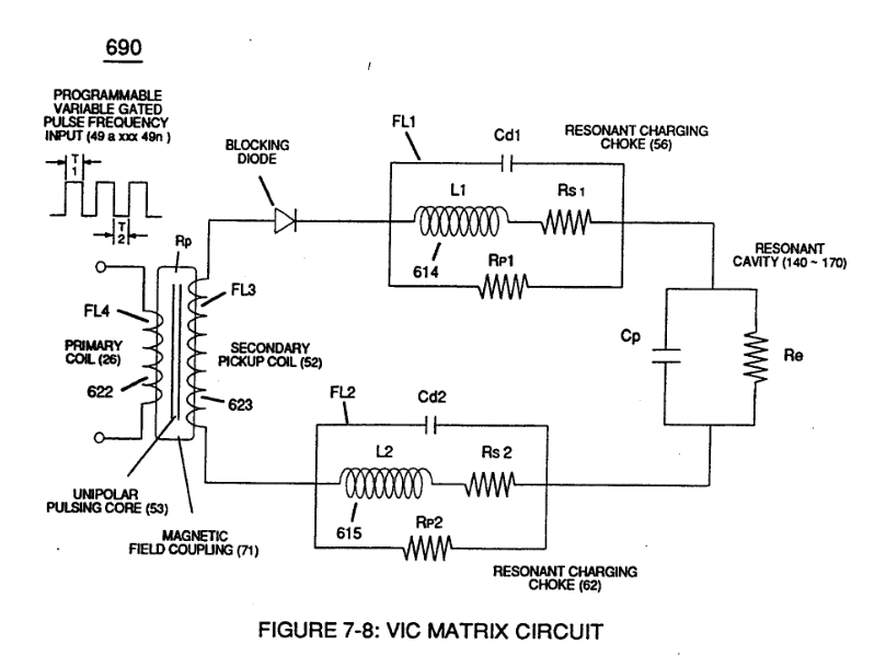
… de (55) to encourage and make use of "Electron Bounce" phenomena (700) of Figure (7-9) to help promote Step Charging Effect (628) of Figure (7-7) by preventing electrical discharge of Resonant Cavity (140 - 170) since Blocking Diode functions as an "Open" switch during Pulse Off-time;
Inductance Reactance (Rs - Cd - FL) 2×
-
Resonant Cavity (140 -170)
… riction (Rp1/Rp2) to both Inductor Chokes (56/62) but automatically increases voltage potential (xxx V g xxx Vh xxx Vn) of opposite voltage intensity of equal magnitude (66/67) across Resonant Cavity (140 -170)
-
Resonant Cavities (140 -170)
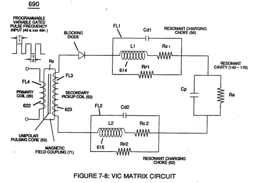
… -1) as to (620) of Figure (7-1) without amp "influxing" (inhibiting amp flow) between Positive Voltage Potential (66) and Negative Voltage Potential (67) electrically applied across Resonant Cavities (140 -170).
In-Line Circuit Components 1×
-
Resonant Capacitor (140 -170)
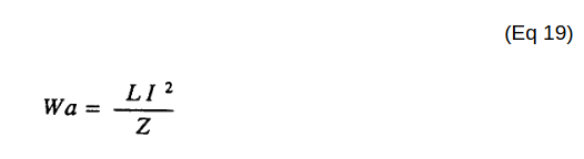
Lengthening Inductor (L1/L2) lengths applies an even higher Voltage Potential (66/67) across Resonant Capacitor (140 -170) (ER) since Inductance Reactance "Stores" Energy and, is expressed by:
Capacitance Reactance 2×
-
Resonant Capacitor (140 -170)
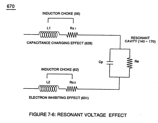
Plate Inductance (Lc) is Inductance Reactance of Inductor (L1 ) and Inductance Reactance of Inductor (L2) in series with Resonant Capacitor (140 -170) of Figure (7-6) as to (690) of Figure (7-8).
-
Resonant Capacitor (140 -170)
Resonant Capacitor (140 -170) of Figure (7-6)
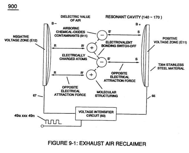
WFC Exhaust Air Reclaimer 1×
-
Gas Resonant Cavity (140)
Likewise, other chemical-oxide gas molecule (s) such as Nitrogen Dioxide N02 (940) of Figure (9-5) exposed to Electrical Polarization Process (160) utilizing Gas Resonant Cavity (140) undergoes the same molecule-to-atom separation