(T3)
Unipolar Pulse-Train
Also written Pulse-train · Gated Pulse-Frequency · Voltage Potential
Where it is first named
VIC Voltage Enhancement Circuit (VIC - VB) (620) of Figure (7-1) incorporates the use of stainless steel wire-wrap coils (614/615) to accomplish the formation of unipolar gated pulse-wave (64a xxx T3 xxx 64n) without experiencing "signal distortion" or "signal degradation" (preventing transformer ringing during signal propagation) as elevated voltage levels ( - xx Vc- xx Vd - xx Vn) while allowing the red …
How it is written
- (T1/T2 - T3/T4) 2× with (T1) Duty Cycle of Pulse Train, (T2) Duty Cycle of Pulse Train, (T4) Trigger Pulse Frequency
- (49a xxx 49n - T3 - 49a xxx 49n) 2× with (49) Voltage Pulse frequency
- (64a xxx T3 xxx 64n) 2× with (64) Pulse Train
- (49a xxx T3 xxx 49n) 1× with (49) Voltage Pulse frequency
- (49a xxxx 49n - T3 - 49a xxx 49n) 1× with (49) Voltage Pulse frequency
- (64a/64b - T3 - 64a/64b) 1× with (64) Pulse Train
- (T1/T4 - T3/T2) 1× with (T1) Duty Cycle of Pulse Train, (T4) Trigger Pulse Frequency, (T2) Duty Cycle of Pulse Train
- (49a xx 49n - T3 - 49a xxx 49n) 1× with (49) Voltage Pulse frequency
Drawings 35
-
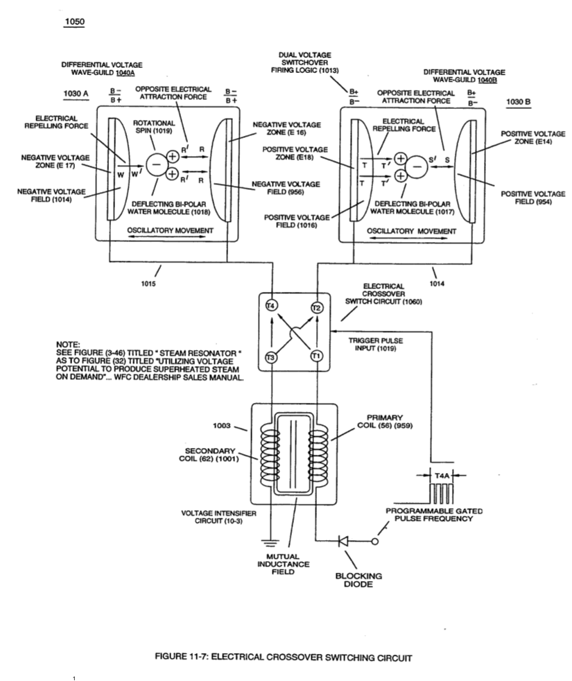
When (B+/B+ - B-/B- / 1030B) switch function is activated, switch terminals (T1/T2 - T3/T4) are closed. · Electrical Crossover Switching Circuit
-
"Voltage Intensity of Opposite Potential" (600) of Figure (6-3) · Voltage Intensifier Coil-Assembly
-
The figure it sits on · WFC 425 - Illustrations
-
Voltage Intensifier Circuit (620) of Figure (7-1) · Instant Explosion of Water
-
(620) of Figure (7-1) · Instant Explosion of Water
-
(620) of Figure (7-1) · Resistance (Rs)
-
Figure (7-13) · Inductance (FL)
-
(600) of Figure (6-3) · Inductance (FL)
-
(614) of Figure (7-1) · Inductance (FL)
-
Inductor (614) of Figure (7-1) · Inductance (FL)
-
(600) of Figure (6-3) · Inductance (FL)
-
(614) of (7-1) · Inductance (FL)
-
Figure (7-1) · Capacitance (Cd)
-
(620) of Figure (7-1) · Inductance Reactance (Rs - Cd - FL)
-
Choke-Coil (62) of Figure (7-1) · Transformer Action
-
(see 740 of Figure 7-13) · Voltage Amplitude Switch-Off
-
The figure it sits on · WFC 426 - Illustrations
-
The figure it sits on · WFC 426 - Illustrations
-
The figure it sits on · 8-1 - Propagating "Resonant Action" By Voltage Tickling of State Space
-
(770) of Figure(8-1) · 8-2 - Traveling Voltage Wave-Guides
-
(770) of Figure (8-1) · 8-3 - Electrical Voltage-Pulse Wave-Transmission
-
(770 A) of Figure (8-1) · 8-4 - State Space (Sp)
-
(770 B) of Figure (8-1) · 8-4 - State Space (Sp)
-
(585) of Figure (8-1) · 8-4 - State Space (Sp)
-
(770A) of Figure (8-1) · 8-5 - Energy Vectoring (Ev)
-
(612) of Figure (8-1) · 8-5 - Energy Vectoring (Ev)
-
(620) of Figure (7-1) · 8-6 - VIC Voltage Sync-Pulse Circuit
-
The figure it sits on · WFC 427 Illustrations
-
"Voltage Tickling of State Space" (770A) of Figure (8-1) · WFC Exhaust Air Reclaimer
-
"Voltage Tickling of State Space" (770B) of Figure (8-1) · WFC Exhaust Air Reclaimer
-
"Resonant Charging Choke" (56) of Figure (7-1) · Propagating Electrical Stress
-
Dynamic Electrical Charging Effect (612) of Figure (8-1) · Propagating Electrical Stress
-
(620) of figure (7-1) · Voltage to Amp Differential Ratio
-
The figure it sits on · Quartz Tube Configuration & Operational Parameters
-
... establishing variable Dynamic Electrical Charging Effect (612). · Quartz Tube Configuration & Operational Parameters
Where it is named · 14
Instant Explosion of Water 4×
-
VIC Voltage Enhancement Circuit (VIC - VB) (620) of Figure (7-1) incorporates the use of stainless steel wire-wrap coils (614/615) to accomplish the formation of unipolar gated pulse-wave (64a xxx T3 xxx 64n) without experiencing "signal distortion" or "signal degradation" (preventing transformer ringing during signal propagation) as elevated voltage levels ( - xx Vc- xx Vd - xx Vn) while allowing the red …
-
... allowing the formation of an gated pulse-frequency pulse-train (64a/64b - T3 - 64a/64b) when pulse off-time (T3) is greater than time-period (T2)
-
... allowing the formation of an gated pulse-frequency pulse-train (64a/64b - T3 - 64a/64b) when pulse off-time (T3) is greater than time-period (T2)
-
Unipolar Pulse-Train (64a xxx T3 xxx 64n)
... input-signal (49a xxx 49n) being a Pulse-Train where (T2) pulse offtime (T2) is adjusted to allow Unipolar Pulse-Train (64a xxx T3 xxx 64n)
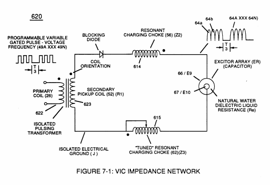
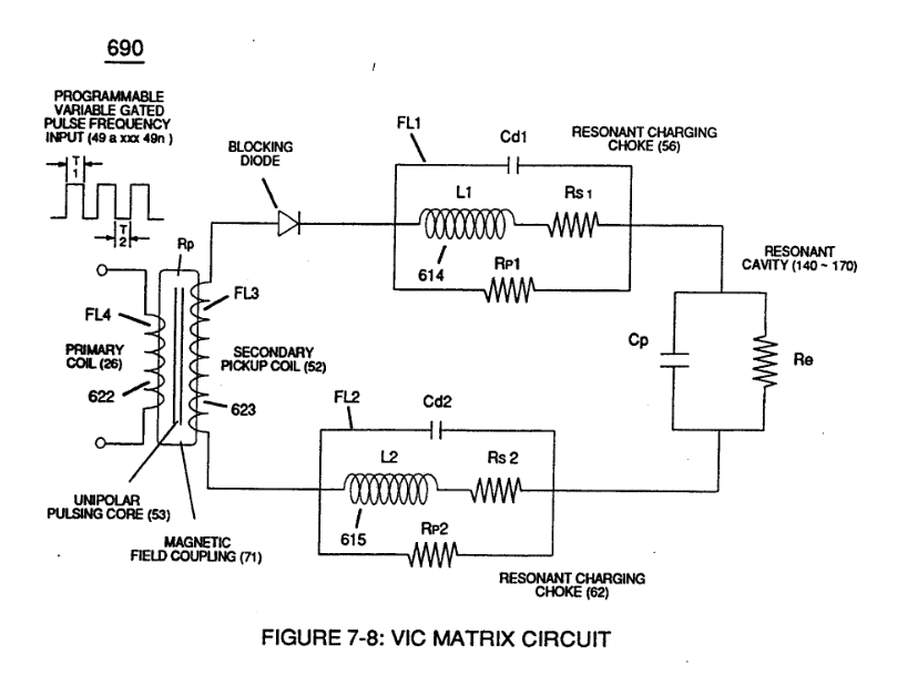
In-Line Circuit Components 2×
-
Gated Pulse-Frequency (49a xxx 49n - T3 - 49a xxx 49n)
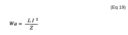
Inductance Reactance directly determines "Stored" Energy (Wa) which is controlled by input Voltage Potential attenuated or varied by way of Voltage Amplitude (Vo xxx Va xxx V b - Vf xxx Vg xxx Vn) of Figure (7-13) and/or Gated Pulse-Frequency (49a xxx 49n - T3 - 49a xxx 49n), or both.
-
Voltage Potential (49a xxxx 49n - T3 - 49a xxx 49n)
Gated Pulse-Frequency of applied Voltage Potential (49a xxxx 49n - T3 - 49a xxx 49n)
Transformer Action 1×
-
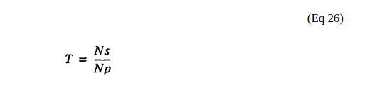
(Ip) is the amount of current flow in the Primary Coil-Winding (26) when electrically "energized" during pulsing operations (49a xxx 49n - T3 - 49a xxx 49a).
Electron Bounce Phenomenon 2×
-
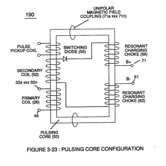
… closed-loop magnetic pulsing core (53) of Figure (190) penetrates Inductance coil-windings (52 - 56 - 62) simultaneously during each and every pulse on-time (T1a xxx T1n) as programmable pulse-train (49a xxx 49n T3 - 49a xxx 49n) is adjusted to "Tune - in" to the dielectric property of Water (Re)
-
... producing Dynamic Voltage Potential (600) of Figure (6-3) during repetitive pulsing (49a xxx 49n - T3 - 49a xxx 49n)

Voltage Amplitude Switch-Off 1×
-
Pulse-train (49a xx 49n - T3 - 49a xxx 49n)
Switching the member of Secondary Coil-Array (505a xxx 505n) maximizes electrical power transfer from Primary Coil (26) to Secondary Coil (52) by keeping Voltage Amplitude of Pulse-train (49a xx 49n - T3 - 49a xxx 49n) constant.
8-5 - Energy Vectoring (Ev) 1×
-
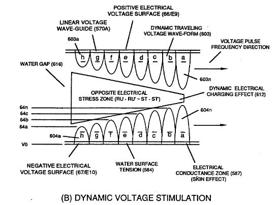
... producing Dynamic Electrical Charging Effect (612) of Figure (8-1) that increases Electrical Stress Pressure (Espa + Espb + Espc, and so on) continually during each gated voltage pulsing cycle (49a xxx T3 xxx 49n).
Electrical Crossover Switching Circuit 3×
-
When (B+/B+ - B-/B- / 1030B) switch function is activated, switch terminals (T1/T2 - T3/T4) are closed.
-
Switch position (T1/T4 - T3/T2) reverses voltage polarity once switch function (T1/T2 - T3/T4) goes to close position after Switch Logic Function (1013) becomes an open circuit
-
Switch position (T1/T4 - T3/T2) reverses voltage polarity once switch function (T1/T2 - T3/T4) goes to close position after Switch Logic Function (1013) becomes an open circuit