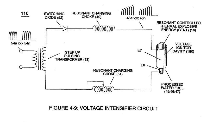
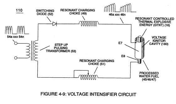
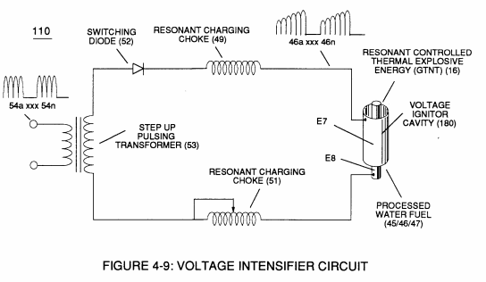
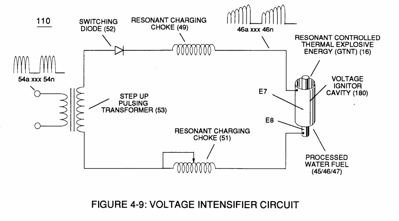
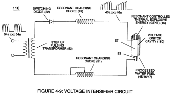
Figure (4-9)
Voltage Intensifier Circuit
Also written Digital Gate Inject Crk't S
How it is written
- (4-9) 17×
Drawings 6
-
Captioned as this figure · Electronic Circuit Design
-
Figure (4-9) · Water Fuel Injection System - Page 2
-
(110) of Figure (4-9) · In Application of Usage
-
(110) of Figure (4-9) · Resistance (Rs)
-
Voltage Intensifier Circuit (110) of Figure (4-9) · WFC Exhaust Air Reclaimer
-
Blocking Diode (52) of Figure (4-9) · Propagating Electrical Stress
On this figure 8
- 14 Response-Time
- 16 Flame Projection
- 52 Secondary Coil
- 80 Circuit
- 93 Water Bath Atoms
- 110 Voltage Intensifier Circuit
- EPA U.S. Environmental Protection Agency
- Re Water
Where it is named · 17
Water Fuel Injection System - Page 2 6×
-
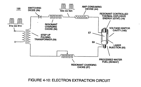
To elevate Energy-flame-temperature still further, simply increase fluid-displacement (46/47) while maintaining or reducing the volume flow rate of non-combustible gases (45) during an increase of applied voltage amplitude (V0 xxx Vo) of Figure (4-2) as to Voltage Intensifier Circuit (110) of Figure (4-9) and Electron Extraction Circuit (120) of Figure (4-10).
-
Figure (4-9)
-
Voltage Igniter Stage (180) of Figure (4-5) as to Voltage Intensifier Circuit (110) Figure (4-9) as to Extraction Circuit (10) of Figure (4-10) performs several functions simultaneously to initiate and trigger thermal explosive energy-yield (gtnt) (16) beyond normal gas burning levels:
-
Figure (4-9)
-
... which not only separates and splits the unlike atoms of the water molecule but also causes the unlike atoms (hydrogen atoms 77a /77b and oxygen atom 76) to experience electron ejection (230) of Figure (3-30) as to (71) of Figure (4-10) since voltage intensifier circuit (110) of Figure (4-9) inhibits and prevents electron flow to enter into gas ignition process (180), as further illustrated in Figure (4-8).
-
Figure (4-9)
Water Fuel Injection System - Page 3 2×
-
… igure 1-15) (see WFC memo 420) to cause the resultant highly energized and mass destabilized combustible gas atoms (93a xxx 93n) of Figure (4-10) to perform Hydrogen Fracturing Process (80) of Figure (4-9) when electrostatic force (14/16) thermally ignites (kinetic agitation) destabilized water-fuel mixture (93a xxx 93n) under gas compression
-
Figure (4-9)
In Application of Usage 2×
-
The Voltage Intensifier Circuit (110) of Figure (4-9) brings on the "Electrical Polarization Process" (160) of Figure (3-26) that switches off the covalent bond (550) of Figure (5-8) of the water molecule without amp influxing.
-
(110) of Figure (4-9)
Resistance (Rs) 2×
-
... allowing the dielectric value of Water (Re) to be a part of Voltage Intensifier Circuit (110) of Figure (4-9) capability of restricting amp flow during Voltage Pulsing Operation (49a xxx 49n) of (620) of Figure (7-1) as to VIC Matrix Circuit (690) of Figure (7-8)
-
(110) of Figure (4-9)
WFC Exhaust Air Reclaimer 3×
-
… Environmental Protection Agency (EPA) clean Air Act similar in construction to Voltage Intensifier Circuit (110) of Figure (4-9), WFC Exhaust Air Reclaimer (900) of Figure (9-1) utilizes opposite electrical attraction force (RR' - SS') of voltage potential (Va xxx Vn) to separate the atoms of the Nitric Oxide NO molecule (typi …
-
Voltage Intensifier Circuit (110) of Figure (4-9)
-
This is accomplished since the Voltage Intensifier Circuit (110) of Figure (4-9) is pulsed sensitive (49a xxx 49n) to tune-in to the dielectric properties of the airborne gas-molecule to not only activate Covalent Switch-Off phenomenon (550) of Figure (5-8) by restricting amp inf …
Propagating Electrical Stress 2×
-
Blocking Diode (52) of Figure (4-9) as to Figure (1-1) allows unipolar pulse-wave to go more positive on each pulse-cycle since the Blocking Diode (52) prevents the Resonant Cavity (Cp) from discharging during pulse off-time, as so illustrated in Figure (1-4) as to (60) of Figure (3-22)
-
Blocking Diode (52) of Figure (4-9)