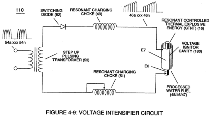
(110)
Voltage Intensifier Circuit
Also written Electronic Circuit · Resonant Pulsing Circuit · Pulse Indicator circuit
Where it is first named
To further prevent voltage fluctuation during resonant action, Phase Lock Loop technique of Pulse Indicator circuit (110) is utilized during pulsing operations.
How it is written
- (110) 17×
Drawings 23
-
Stanley A. Meyer Page17 of 28 · WFC 417 — WFC 417
-
Stanley A. Meyer Page 21 of 28 · WFC 417 — WFC 417
-
Operational Parameters · RE: Electrical Particle Generator
-
The Electron Extraction Process (BB) is, hereinafter, called "The GAS RESONANT CAVITY," as illustrated in Figure 1-7 as to Figure 20JX. · Electron Extraction Process
-
The Positive Electrical Voltage Field (E3) and Negative Electrical Voltage Fields (E4) are triggered "Simultaneously" during the same duty-pulse. · Electron Extraction Process
-
Figure (3-5) · Acceleration Control Circuit (30)
-
Analog Voltage Circuit (40), as shown in Figure (3-5) · Acceleration Control Circuit (30)
-
Figure (3-5) · Acceleration Control Circuit (30)
-
Figure (3-5) · Analog Voltage generator (40)
-
To further prevent voltage fluctuation during resonant action, Phase Lock Loop technique of Pulse Indicator circuit (110) is utilized during pulsing operations. · Resonant Action
-
Figure (3-5) · Laser Distributor
-
Carries this number · WFC 422DA - Illustrations
-
Carries this number · Differential Air-Gas Inlet Control
-
Carries this number · Differential Air-Gas Inlet Control
-
Electronic Circuit (110) of Figure (7) · Water Fuel Injector (Taper Resonant Cavity Chamber)
-
2-4 Positive Probe Assembly · Water Fuel Injector Illustrations
-
Carries this number · Steam Resonator Assembly
-
Figure (4-9) · Water Fuel Injection System - Page 2
-
(110) of Figure (4-9) · In Application of Usage
-
(110) of Figure (4-9) · Resistance (Rs)
-
Voltage Intensifier Circuit (110) of Figure (4-9) · WFC Exhaust Air Reclaimer
-
Blocking Diode (52) of Figure (4-9) · Propagating Electrical Stress
-
The figure it sits on · Electronic Circuit Design
Where it is named · 17
Resonant Action 1×
-
Pulse Indicator circuit (110)
To further prevent voltage fluctuation during resonant action, Phase Lock Loop technique of Pulse Indicator circuit (110) is utilized during pulsing operations.
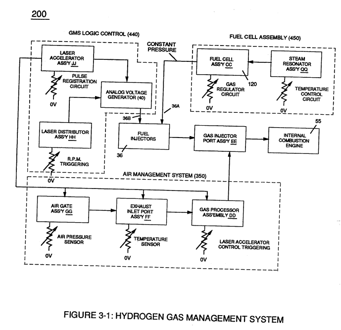
Water Fuel Injection System 3×
-
Voltage Intensifier Circuit (110)
To elevate Energy-flame-temperature still further, help increase fluid-displacement (46/47) while maintaining or reducing the volume flow rate of non-combustible gases (45) during an increase of applied voltage amplitude (Vo x Vn) of Figure (32) as to Voltage Intensifier Circuit (110) of Figure (7) and Electron Extraction Circuit (120) of Figure (8).
-
Voltage Intensifier Circuit (110)
Voltage Igniter Stage (180) of Figure (3B) as to Voltage Intensifier Circuit (110) Figure (7) as to Extraction Circuit (120) of Figure (8) performs several functions simultaneously to initiate and trigger thermal explosive energy-yield (gtnt) (16) beyond normal gas burning levels:
-
… molecule but also causes the unlike atoms (hydrogen atoms 77a / 77b and oxygen atom 76) to experience electron ejection (230) of Figure (29) as to (71) of Figure (8) since voltage intensifier circuit (110) of Figure (7) inhibits and prevents electron flow to enter into gas ignition process (180), as further illustrated in Figure (6).
Water Fuel Injector (Taper Resonant Cavity Chamber) 3×
-
Electronic Circuit (110)
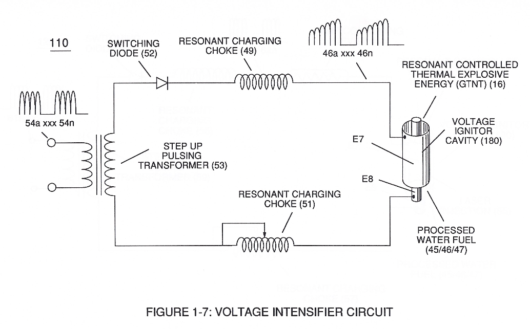
Incoming pulse-train (210a xxx 210n) is adjusted to "tune-in" to the Dielectric Properties of Water (47) which allows Resonant Action (see WFC Memo 424, once again) to occur since the Dielectric property of water (78.54 value) becomes a integral part of Electronic Circuit (110) of Figure (7) as to (220) of Figure (18)
-
Resonant Pulsing Circuit (110)
... forming a capacitor (E7 / E8) in series with Resonant Charging Chokes (56/57) placed on opposite sides of Resonant Cavity Zone (35) as to Figure (7) and (8) . . . forming a Resonant Pulsing Circuit (110) of Figure (7) with step-up Pulsing Transformer (33/36), as shown in (220) of Figure (18).
Water Fuel Injection System - Page 2 3×
-
Voltage Intensifier Circuit (110)
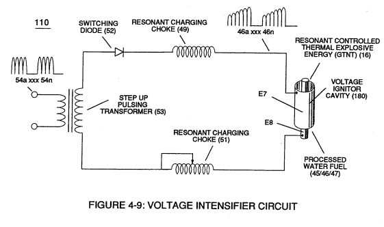
To elevate Energy-flame-temperature still further, simply increase fluid-displacement (46/47) while maintaining or reducing the volume flow rate of non-combustible gases (45) during an increase of applied voltage amplitude (V0 xxx Vo) of Figure (4-2) as to Voltage Intensifier Circuit (110) of Figure (4-9) and Electron Extraction Circuit (120) of Figure (4-10).
-
Voltage Intensifier Circuit (110)
Voltage Igniter Stage (180) of Figure (4-5) as to Voltage Intensifier Circuit (110) Figure (4-9) as to Extraction Circuit (10) of Figure (4-10) performs several functions simultaneously to initiate and trigger thermal explosive energy-yield (gtnt) (16) beyond normal gas burning levels:
-
voltage intensifier circuit (110)
... which not only separates and splits the unlike atoms of the water molecule but also causes the unlike atoms (hydrogen atoms 77a /77b and oxygen atom 76) to experience electron ejection (230) of Figure (3-30) as to (71) of Figure (4-10) since voltage intensifier circuit (110) of Figure (4-9) inhibits and prevents electron flow to enter into gas ignition process (180), as further illustrated in Figure (4-8).
In Application of Usage 2×
-
Voltage Intensifier Circuit (110)
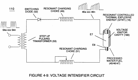
The Voltage Intensifier Circuit (110) of Figure (4-9) brings on the "Electrical Polarization Process" (160) of Figure (3-26) that switches off the covalent bond (550) of Figure (5-8) of the water molecule without amp influxing.
-
(110) of Figure (4-9)
Resistance (Rs) 2×
-
Voltage Intensifier Circuit (110)
... allowing the dielectric value of Water (Re) to be a part of Voltage Intensifier Circuit (110) of Figure (4-9) capability of restricting amp flow during Voltage Pulsing Operation (49a xxx 49n) of (620) of Figure (7-1) as to VIC Matrix Circuit (690) of Figure (7-8)
-
(110) of Figure (4-9)
WFC Exhaust Air Reclaimer 3×
-
Voltage Intensifier Circuit (110)
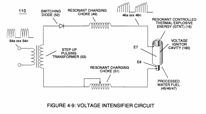
… Environmental Protection Agency (EPA) clean Air Act similar in construction to Voltage Intensifier Circuit (110) of Figure (4-9), WFC Exhaust Air Reclaimer (900) of Figure (9-1) utilizes opposite electrical attraction force (RR' - SS') of voltage potential (Va xxx Vn) to separate the atoms of the Nitric Oxide N …
-
Voltage Intensifier Circuit (110)
Voltage Intensifier Circuit (110) of Figure (4-9)
-
Voltage Intensifier Circuit (110)
This is accomplished since the Voltage Intensifier Circuit (110) of Figure (4-9) is pulsed sensitive (49a xxx 49n) to tune-in to the dielectric properties of the airborne gas-molecule to not only activate Covalent Switch-Off phenomenon (550) of Figure (5-8) by res …