(71) · also written as a run, 71a xxx 71n
Magnetic Field Coupling
Also written magnetic field · unipolar magnetic field coupling · pulsating magnetic field · Secondary Voltage Level · primary coupling field · Magnetic Induction · lines of force · voltage levels
Where it is first named
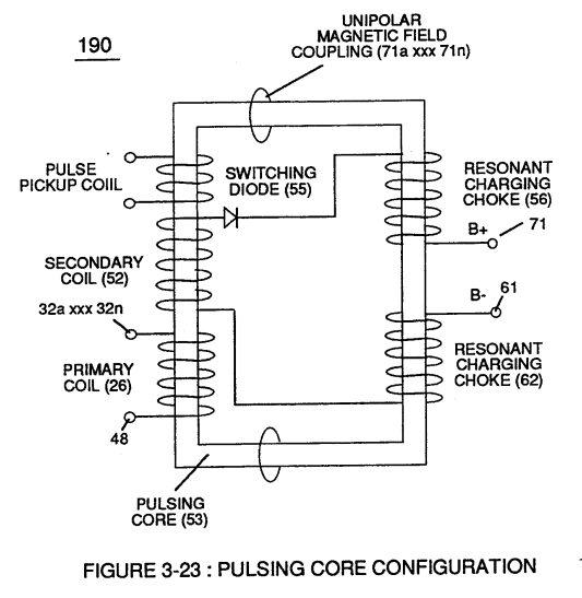
Amp restriction beyond "resonant action" occurs when unipolar magnetic field coupling (71) of Figure (3-23) is allowed to simultaneously drop (pulsating magnetic field) across both resonant charging chokes (56/62) during pulsing operations since electron mass is an electromagnetic entity which is subject to inductor fields (56/62) produced by pulsating magnetic field (71a xxx 71n) of Figure (3-23).
How it is written
- (71) 14×
- (71a xxx 71n) 5×
- (71 - 511 - 512) 1× with (511) Inductance Coupling field, (512) Inductance Coupling field
- (71a - 71n) 1×
- (71a xx 71n) 1×
- (Rp/71) 1× with (Rp) Transformer Magnetic Field
71a xxx 71n is Meyer's shorthand for a run of the same thing: 71a is the first, 71n the last, and the x's stand for however many lie between. Every stage of the run is this one numeral.
Drawings 88
-
Figure (3-24) · Voltage Amplitude Control Circuit (50)
-
Figure (3-26) · Voltage Intensifier Circuit (60)
-
Figure (3-25) · Voltage Intensifier Circuit (60)
-
Figure (3-23) · Voltage Intensifier Circuit (60)
-
Figure (3-23) · Voltage Dynamics
-
In both cases, electrical charge deflection or movement is directly related to applied voltage (65). · Voltage Dynamics
-
Figure (3-29) · Electrically Charged Water Molecule
-
Figure (3-26) · Electrically Charged Water Molecule
-
Figure (3-24) · Electrical Polarization process
-
Figure (3-30) · Resonant Action
-
Carries this number · WFC 422DA - Illustrations
-
Carries this number · WFC 422DA - Illustrations
-
Carries this number · WFC 422DA - Illustrations
-
Carries this number · WFC 422DA - Illustrations
-
Carries this number · WFC 422DA - Illustrations
-
Carries this number · WFC 422DA - Illustrations
-
Carries this number · Electronic Circuit Design
-
Carries this number · Water Fuel Injector (Taper Resonant Cavity Chamber)
-
Carries this number · Funneling Effect
-
thereby, attenuating voltage amplitude (voltage intensity) beyond Secondary Coil (53) voltage levels (71), as illustrated in (220) of Figure (18). · Funneling Effect
-
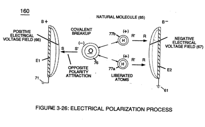
(160) of Figure (3-26) · Water Fuel Injection System - Page 1
-
Carries this number · Energy Pumping Action
-
(85) of Figure (3-26) · In Application of Usage
-
(160) of Figure (3-26) · In Application of Usage
-
coil-structures (580) of Figure (6-1) · Voltage Intensifier Coil-Assembly
-
(190) of Figure (3-23) · Tri - Coil Construction
-
Carries this number · VIC Matrix Circuit
-
(700) of Figure (7-9) · Instant Explosion of Water
-
(57 of Figure 3- 25 ~35 of Figure 6-2) · Instant Explosion of Water
-
(T2) of Figure (7-8) · Instant Explosion of Water
-
Figure (7-8) · Resistance (Rs)
-
(85) of Figure (3-26) · Resistance (Rs)
-
(690) of Figure (7-8) · Resistance (Rs)
-
(580) of Figure (6-1) · Inductance (FL)
-
(710) of Figure (7-10) · Inductance (FL)
-
(690) of Figure (7-8) · Inductance (FL)
-
Figure (3-24) · Inductance (FL)
-
(710) of Figure (7-10) · Capacitance (Cd)
-
(690) of Figure (7-8) · Capacitance (Cd)
-
(690) of Figure (7-8) · Inductance Reactance (Rs - Cd - FL)
-
"Electron Bounce" phenomenon (700) of Figure (7-9) · Inductance Reactance (Rs - Cd - FL)
-
Inductance Pulsing-Core (190) of Figure (3-23) · Inductance Reactance (Rs - Cd - FL)
-
Figure (7-8) · Inductance Reactance (Rs - Cd - FL)
-
(690) of Figure (7-8) · Taper Resonant Capacitor (ERt)
-
690 of Figure 7-8 · Circuit Resistance
-
(710) of Figure (7-10) · Transformer Action
-
Inductance Charging Effect (660) of Figure (7-5) · Transformer Action
-
"Electron Clustering" (Grouping/collecting negative charged particles at a given point) (700) of Figure (7-9) · Transformer Action
-
Carries this number · Electron Bounce Phenomenon
-
Voltage Dynamics (220) of Figure (3-29) · Electron Bounce Phenomenon
-
(52) of Figure (7-8) · Electron Bounce Phenomenon
-
(700) of Figure (7-9) · Electron Bounce Phenomenon
-
Carries this number · WFC 426 - Illustrations
-
Carries this number · WFC 426 - Illustrations
-
Carries this number · WFC 426 - Illustrations
-
(580) of Figure (6-1) (WFC memo 425) · 8-2 - Traveling Voltage Wave-Guides
-
(690) of Figure (7-8) · 8-2 - Traveling Voltage Wave-Guides
-
(631) of Figure (7-9) · 8-3 - Electrical Voltage-Pulse Wave-Transmission
-
(52) of Figure (7-8) · 8-3 - Electrical Voltage-Pulse Wave-Transmission
-
(Cp) of Figure (7-8) · 8-4 - State Space (Sp)
-
(170) of Figure (3-25) · 8-4 - State Space (Sp)
-
(690) of Figure (7-8) · 8-6 - VIC Voltage Sync-Pulse Circuit
-
(Cp) of (7-8) · 8-6 - VIC Voltage Sync-Pulse Circuit
-
Carries this number · WFC Exhaust Air Reclaimer
-
Voltage Dynamics (220) of Figure (3-29) · WFC Exhaust Air Reclaimer
-
(690) of Figure (7-8) · Propagating Electrical Stress
-
(160) of Figure (3-26) · Propagating Electrical Stress
-
(580) of Figure (6-1) · Voltage to Amp Differential Ratio
-
The figure it sits on · Gated Pulse Frequency generator (80)
-
The figure it sits on · WFC 422DA - Illustrations
-
The figure it sits on · Electronic Circuit Design
-
Figure (25) · Water Fuel Injector (Taper Resonant Cavity Chamber)
-
Figure (4-10) · Water Fuel Injection System - Page 2
-
Voltage Intensifier Circuit (620) of Figure (7-1) · Instant Explosion of Water
-
(620) of Figure (7-1) · Instant Explosion of Water
-
(620) of Figure (7-1) · Resistance (Rs)
-
(614) of Figure (7-1) · Inductance (FL)
-
Inductor (614) of Figure (7-1) · Inductance (FL)
-
(614) of (7-1) · Inductance (FL)
-
Figure (7-1) · Capacitance (Cd)
-
(620) of Figure (7-1) · Inductance Reactance (Rs - Cd - FL)
-
(580) of Figure (6-1) · Multi-layer Coil
-
Choke-Coil (62) of Figure (7-1) · Transformer Action
-
The figure it sits on · WFC 426 - Illustrations
-
(620) of Figure (7-1) · 8-6 - VIC Voltage Sync-Pulse Circuit
-
"Resonant Charging Choke" (56) of Figure (7-1) · Propagating Electrical Stress
-
(620) of figure (7-1) · Voltage to Amp Differential Ratio
-
The figure it sits on · WFC 429 - Illustrations
Where it is named · 23
Voltage Intensifier Circuit (60) 2×
-
unipolar magnetic field coupling (71)
Amp restriction beyond "resonant action" occurs when unipolar magnetic field coupling (71) of Figure (3-23) is allowed to simultaneously drop (pulsating magnetic field) across both resonant charging chokes (56/62) during pulsing operations since electron mass is an electromagnetic entity which is subject to inductor fields (56/62) produced by pulsating magnetic field (71a xxx 71n) of Figure (3-23).
-
pulsating magnetic field (71a xxx 71n)
Amp restriction beyond "resonant action" occurs when unipolar magnetic field coupling (71) of Figure (3-23) is allowed to simultaneously drop (pulsating magnetic field) across both resonant charging chokes (56/62) during pulsing operations since electron mass is an electromagnetic entity which is subject to inductor fields (56/62) produced by pulsating magnetic field (71a xxx 71n) of Figure (3-23).
Water Fuel Injection System 1×
-
… y separates and splits the unlike atoms of the water molecule but also causes the unlike atoms (hydrogen atoms 77a / 77b and oxygen atom 76) to experience electron ejection (230) of Figure (29) as to (71) of Figure (8) since voltage intensifier circuit (110) of Figure (7) inhibits and prevents electron flow to enter into gas ignition process (180), as further illustrated in Figure (6).
Water Fuel Injector (Taper Resonant Cavity Chamber) 1×
-
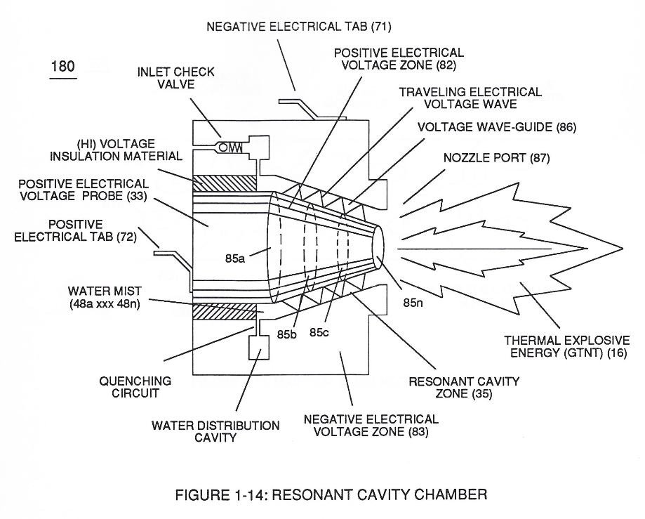
This induced voltage phenomenon encourages and therefore prevents resonant pulse frequency (58) from being impaired or altered while being electrically transmitted to Resonant Cavity (180) of Figure (14) via electrical tabs (71) and (72) of Figure (14).
Funneling Effect 2×
-
Secondary Voltage Level (71)
To return or lower Voltage Intensity (xxx Vmn) to Secondary Voltage Level (71), once again, inductance core-slug (73) (magnetic core material) advances (via solenoid Control 74) toward, passes through inside coil-wrap (250) in linear manner to "Switch-Off" each adjacent coil-st …
-
voltage levels (71)
thereby, attenuating voltage amplitude (voltage intensity) beyond Secondary Coil (53) voltage levels (71), as illustrated in (220) of Figure (18).
Water Fuel Injection System - Page 2 1×
-
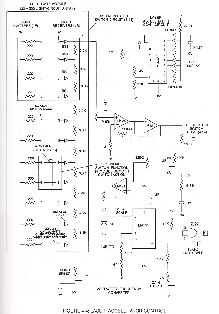
... which not only separates and splits the unlike atoms of the water molecule but also causes the unlike atoms (hydrogen atoms 77a /77b and oxygen atom 76) to experience electron ejection (230) of Figure (3-30) as to (71) of Figure (4-10) since voltage intensifier circuit (110) of Figure (4-9) inhibits and prevents electron flow to enter into gas ignition process (180), as further illustrated in Figure (4-8).
Water Fuel Injector 1×
-
As incoming gated pulse-train (46a xxx 46n) of Figure (3-17) is electronically "tuned" to adjust pulse off- time (T2) to compensate for "rise" and "fall" of magnetic field coupling (71a xxx 71n) for a predetermined resonant pulse-frequency established and determined by the dielectric value of natural water in direct relationship to resonant cavity geometrical configuration
Instant Explosion of Water 1×
-
magnetic field (71)
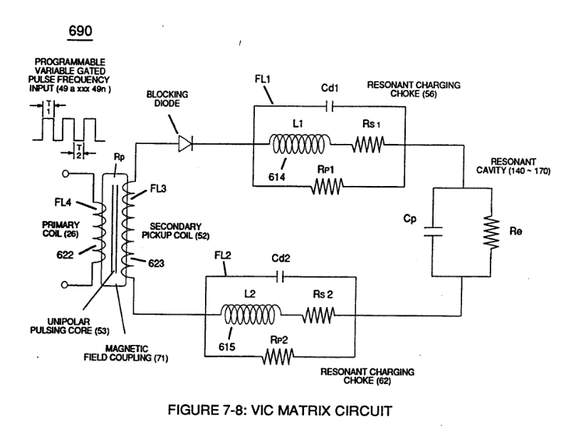
... producing a second unipolar voltage wave-form (64b) during the rise and fall of magnetic field (71), as further illustrated in (620) of Figure (7-1)
Inductance Reactance (Rs - Cd - FL) 2×
-
Electron Inhibiting Effect (631) in direct relationship to Voltage Enhancement Effect (528) is accomplished since stainless steel 430F/FR wire-material is "Electromagnetic Inductive" to incoming electromagnetic flux-lines (71a xxx 71n) (Rp) without (s/s) inductor-wire-coil (L1/L2) becoming permanently magnetized
-
… paralleling and performing the same electromagnetic characteristic of copper wire when it comes to magnetic field reformation (Rp - Rp 1 - Rp2) of Figure (7-8), as further illustrated in electromagnetic coupling fields (71 - 511 - 512) of Figure (6-1) that encourages, brings-on, and perform Voltage Inducement Process (580) of Figure (6-1) as to (620) of Figure (7-1) without amp "influxing" (inhibiting amp flow) between Positive Vol …
Circuit Resistance 1×
-
primary coupling field (71)
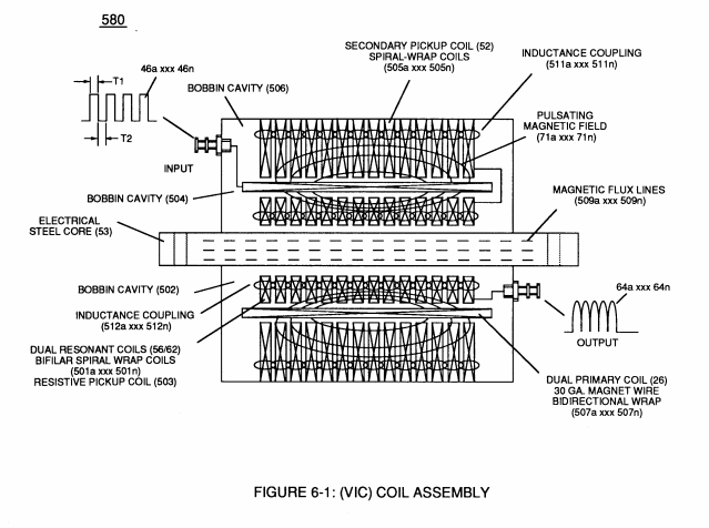
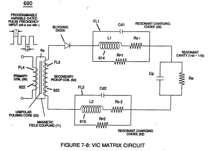
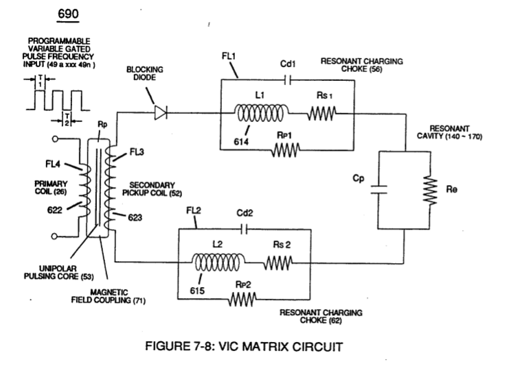
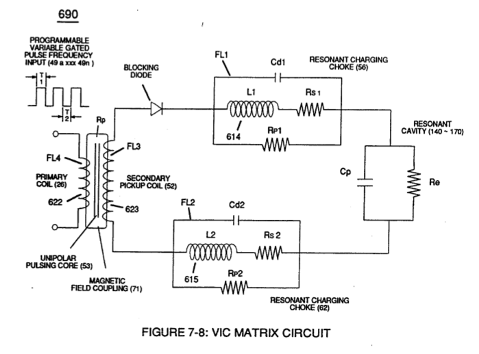
(Rl) is the resistive value of Secondary Pickup Coil (52) of Figure (7-8) plus Magnetic Field strength of primary coupling field (71) in direct relationship to inductance field strength (Rp) which is determined by the number of turns of wire that make up secondary coil-wrap (52),
Transformer Action 4×
-
Magnetic Field Coupling (71)
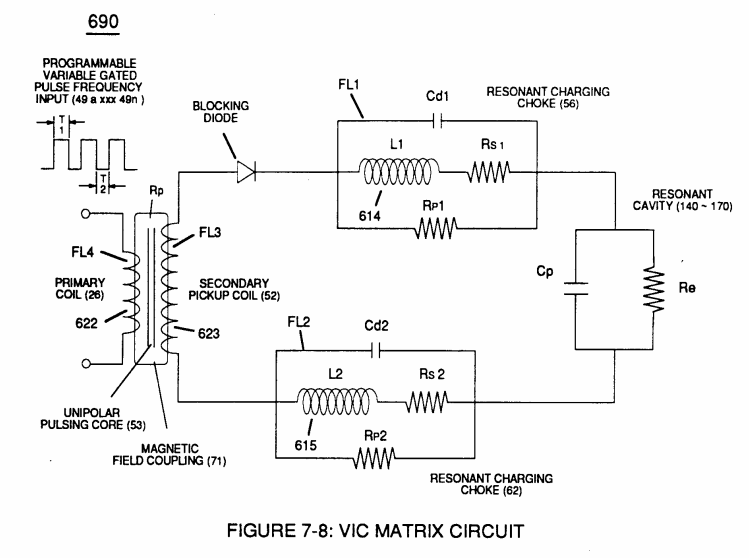
Inductance Core (53) of Figure (6-1) composed of "Grain Oriented" Electrical Steel laminations step up applied Voltage (49) when Magnetic Field Coupling (71) of Figure (7-8) cross over to Secondary Pickup Coil-winding (52) which has more turns of wire than Primary Coil- winding (26) by way of "Eddy" currents that induce magnetic flux lines of forces (71a …
-
… (71) of Figure (7-8) cross over to Secondary Pickup Coil-winding (52) which has more turns of wire than Primary Coil- winding (26) by way of "Eddy" currents that induce magnetic flux lines of forces (71a xxx 71n) emanating away from magnetic core material (53) and caused by Primary Coil (26) being electrically energized during pulsing operations (T1a xx T1n), as illustrated in (690) of Figure (7-8).
-
(71) of Figure (7-8)
-
Magnetic Induction (71a - 71n)
Magnetic Induction (71a - 71n) is determined by Inductance Permeability (μL) of core material (53) along with VIC circuit geometry ability to step up Voltage Potential (Vo - Vn) by way of "Transformer Action", and is expressed in the following equations:
Electron Bounce Phenomenon 4×
-
lines of force (71a xx 71n)
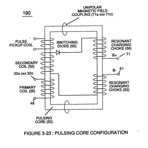
High Voltage Potential of Difference (Vo - Vn) (SS' - 617 -RR') is accomplished when magnetic flux lines of force (71a xx 71n) (Rp) emanating away from closed-loop magnetic pulsing core (53) of Figure (190) penetrates Inductance coil-windings (52 - 56 - 62) simultaneously during each and every pulse on-time (T1a xxx T1n) as …
-
Magnetic Field Coupling (71)
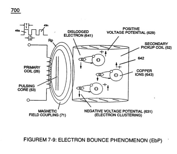
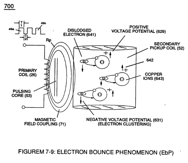
Magnetic Field Coupling (71) of Figure (7-9) entering into and passing through Secondary Coil-winding (52) of Figure (7-8) causes and produces copper ions (643a xxx 643n) (Positive Charged atoms 542a xxx 542n having missing elec …
-
… y Coil-winding (52) of Figure (7-8) causes and produces copper ions (643a xxx 643n) (Positive Charged atoms 542a xxx 542n having missing electrons) when moving external electromagnetic field strength (71a xxx 71n) is sufficient enough to dislodge electromagnetically charged electrons (641a xxx 641n) from copper atoms making up copper wire material (52).
-
Magnetic Field (71)
Once Secondary Coil-winding (52) is de-energized by the removal (collapsing magnetic field during pulse off-time T2 of external Magnetic Field (71), the dislodged electrons (641a xx 641n) return to positive charged copper ions (642a xx 642n)
Mode of Operability 1×
-
Pulse Off-time (T2) of Figure (7-8) as to (620) of Figure (7-1) is adjusted to compensate for the rise and fall of magnetic coupling field (71) to produce applied Unipolar Wave-forms (64a xxx 64n) entering into Wave-guides (35a/35b/35c).
8-3 - Electrical Voltage-Pulse Wave-Transmission 1×
-
… Effect" (631) of Figure (7-9) produces a "Negative Electrical Voltage Intensity (67) in equal magnitude to the "Positive Electrical Voltage Intensity (66) during each/repetitious magnetic pulse-cycle (Rp/71). Remember, Secondary Voltage pickup coil (52) of Figure (7-8) displaces and separates Resonant Charging Chokes (56/62) on opposite end of said Secondary Pickup Coil (52).
WFC Exhaust Air Reclaimer 1×
-
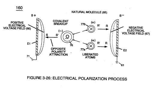
.•• performing the same function as Electrical Polarization Process (160) of Figure (3-26) by which the positive electrical voltage potential (71) attracts the negative charged oxygen atom; while, simultaneously, negative electrical voltage potential (61) attracts the positive charged Nitrogen Atom