(T2) · also written as a run, T2a xxx T2n
Duty Cycle of Pulse Train
Also written Resonant Pulse-train · Pulse Off-time · pulse offtime
Where it is first named
Adjusting Pulse-train (210a xxx 210n) in such a way as to allow pulse off-time (T2) to be synchronized with collapsing and re-formation of electromagnetic field coupling across pulsing transformer (52/53) to produce unipolar pulse frequency (T1a xxx T1n), as illustrated in (220) of Figure (18) as to Figure (17).
How it is written
- (T2) 12×
- (T1/T2 - T3/T4) 2× with (T1) Duty Cycle of Pulse Train, (T3) Unipolar Pulse-Train, (T4) Trigger Pulse Frequency
- (T1 + T2a xxx T1 + T2n) 1× with (T1) Duty Cycle of Pulse Train
- (T1 - T2a xxx T1 – T2n) 1× with (T1) Duty Cycle of Pulse Train
- (T1/T4 - T3/T2) 1× with (T1) Duty Cycle of Pulse Train, (T4) Trigger Pulse Frequency, (T3) Unipolar Pulse-Train
T2a xxx T2n is Meyer's shorthand for a run of the same thing: T2a is the first, T2n the last, and the x's stand for however many lie between. Every stage of the run is this one numeral. A pair before the letters, 583/602a, is a run of two things that go together, one of each per stage.
Drawings 50
-
Carries this number · Electronic Circuit Design
-
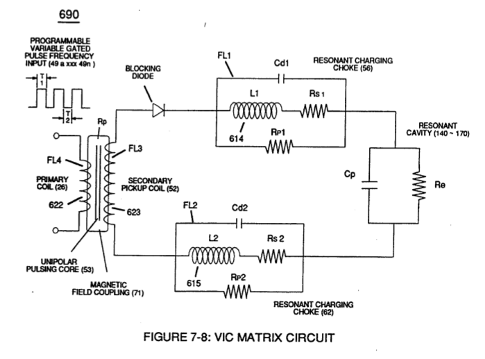
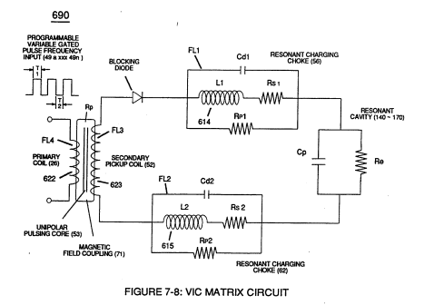
(T2) of Figure (7-8) · Instant Explosion of Water
-
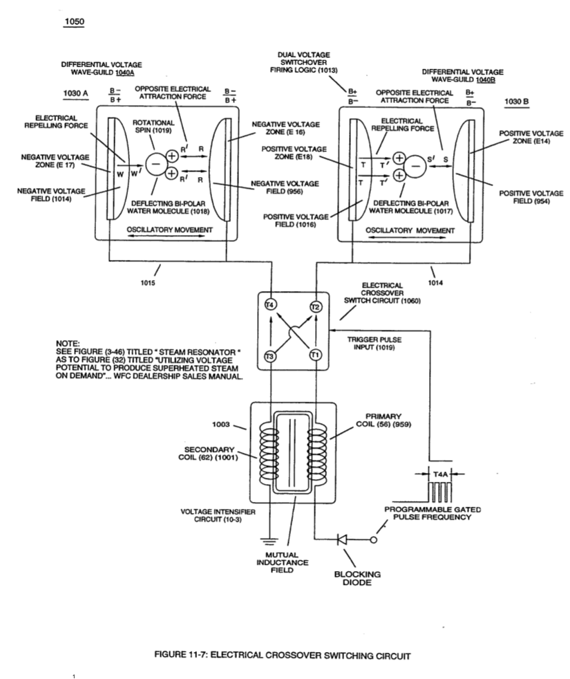
When (B+/B+ - B-/B- / 1030B) switch function is activated, switch terminals (T1/T2 - T3/T4) are closed. · Electrical Crossover Switching Circuit
-
Figure (3-22) · Analog Voltage generator (40)
-
Figure (3-22) · Voltage Amplitude Control Circuit (50)
-
The figure it sits on · Gated Pulse Frequency generator (80)
-
Figure (3-22) · Voltage Intensifier Circuit (60)
-
Figure (3-22) · Voltage Dynamics
-
Voltage Intensifier Circuit (60) of Figure (3-22) · Gas Processor
-
The figure it sits on · WFC 422DA - Illustrations
-
The figure it sits on · WFC 422DA - Illustrations
-
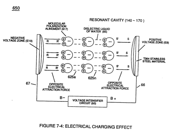
(650) of Figure (7-4) · Amp Inhibiting Circuit Vs Voltage Enhancement
-
The figure it sits on · VIC Matrix Circuit
-
Voltage Intensifier Circuit (60) of Figure (3-22) · Instant Explosion of Water
-
(56/62) of Figure (3-22) · Instant Explosion of Water
-
(628) of Figure (7-7) · Instant Explosion of Water
-
(56) of Figure (3-22) · Instant Explosion of Water
-
Figure (7-8) · Resistance (Rs)
-
(650) of Figure (7-4) · Resistance (Rs)
-
(690) of Figure (7-8) · Resistance (Rs)
-
The figure it sits on · Inductance (FL)
-
(690) of Figure (7-8) · Inductance (FL)
-
(650) of Figure (7-4) · Inductance (FL)
-
(650) of Figure (7-4) · Capacitance (Cd)
-
(690) of Figure (7-8) · Capacitance (Cd)
-
(690) of Figure (7-8) · Inductance Reactance (Rs - Cd - FL)
-
(627) of Figure (7-7) · Inductance Reactance (Rs - Cd - FL)
-
Figure (7-8) · Inductance Reactance (Rs - Cd - FL)
-
(690) of Figure (7-8) · Taper Resonant Capacitor (ERt)
-
"Voltage Deflection" of Figure (7-4) · Capacitance Reactance
-
690 of Figure 7-8 · Circuit Resistance
-
Opposite Electrical Attraction Force (SS' ~ 617 ~ RR' - T3 - SS' ~ 617 - RR') of Figure (7-4) · Electron Bounce Phenomenon
-
(52) of Figure (7-8) · Electron Bounce Phenomenon
-
The figure it sits on · WFC 426 - Illustrations
-
The figure it sits on · WFC 426 - Illustrations
-
The figure it sits on · 8-2 - Traveling Voltage Wave-Guides
-
(690) of Figure (7-8) · 8-2 - Traveling Voltage Wave-Guides
-
(52) of Figure (7-8) · 8-3 - Electrical Voltage-Pulse Wave-Transmission
-
(Cp) of Figure (7-8) · 8-4 - State Space (Sp)
-
(650) of Figure (7-4) · 8-4 - State Space (Sp)
-
(690) of Figure (7-8) · 8-6 - VIC Voltage Sync-Pulse Circuit
-
(650) of Figure (7-4) · 8-6 - VIC Voltage Sync-Pulse Circuit
-
(Cp) of (7-8) · 8-6 - VIC Voltage Sync-Pulse Circuit
-
(690) of Figure (7-8) · Propagating Electrical Stress
-
Voltage Intensifier Circuit (60) of Figure (3-22) · Propagating Electrical Stress
-
The figure it sits on · Propagating Electrical Stress
-
(60) of Figure (3-22) · Propagating Electrical Stress
-
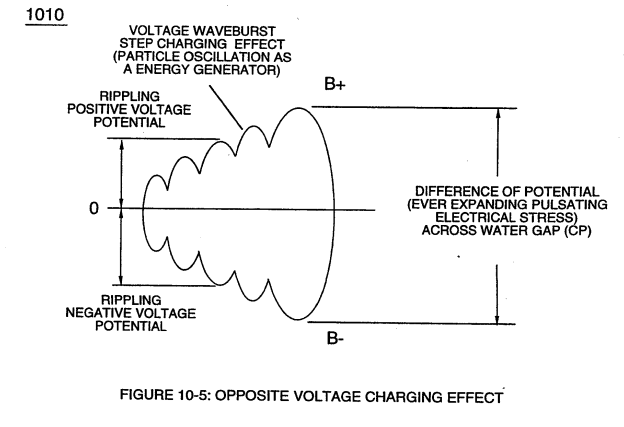
of Figure (10-5) · Voltage to Amp Differential Ratio
-
The figure it sits on · WFC 429 - Illustrations
-
The figure it sits on · WFC 429 - Illustrations
Where it is named · 17
Water Fuel Injector (Taper Resonant Cavity Chamber) 2×
-
Adjusting Pulse-train (210a xxx 210n) in such a way as to allow pulse off-time (T2) to be synchronized with collapsing and re-formation of electromagnetic field coupling across pulsing transformer (52/53) to produce unipolar pulse frequency (T1a xxx T1n), as illustrated in (220) of Figure (18) as to Figure (17).
-
Resonant Pulse-train (T1 + T2a xxx T1 + T2n)
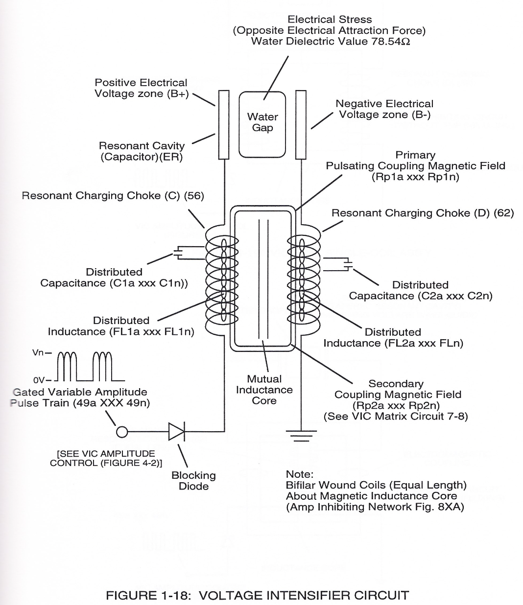
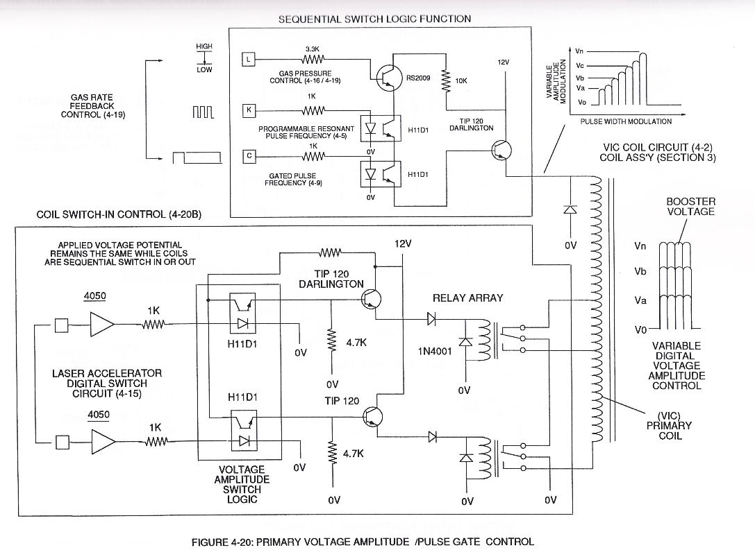
The resultant and newly formed gated Resonant Pulse-train (T1 + T2a xxx T1 + T2n) (58) voltage amplitude (Vo xxx Vn) is, now, attenuated by Sequential Voltage Amplitude Control Circuit (59) once step up Secondary Coil (53) produces a higher voltage level (xxxVL) above incoming pulse-train (210) since Secondary Coil (53) has a greater number of turns of wire.
Water Fuel Injector 1×
-
As incoming gated pulse-train (46a xxx 46n) of Figure (3-17) is electronically "tuned" to adjust pulse off- time (T2) to compensate for "rise" and "fall" of magnetic field coupling (71a xxx 71n) for a predetermined resonant pulse-frequency established and determined by the dielectric value of natural water in direct relationship to resonant cavity geometrical configuration
Instant Explosion of Water 5×
-
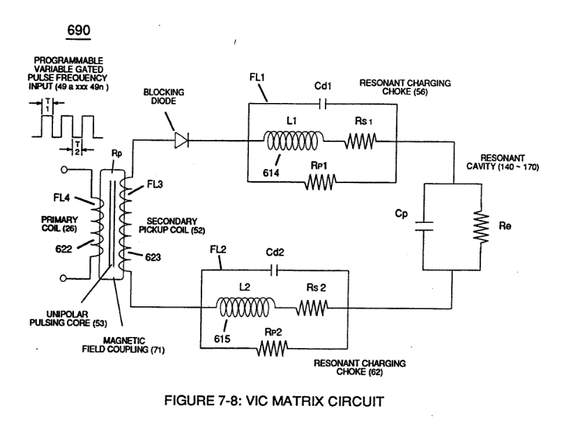
(T2) of Figure (7-8)
-
... allowing the formation of an gated pulse-frequency pulse-train (64a/64b - T3 - 64a/64b) when pulse off-time (T3) is greater than time-period (T2)
-
... input-signal (49a xxx 49n) being a Pulse-Train where (T2) pulse offtime (T2) is adjusted to allow Unipolar Pulse-Train (64a xxx T3 xxx 64n)
-
pulse offtime (T2)
... input-signal (49a xxx 49n) being a Pulse-Train where (T2) pulse offtime (T2) is adjusted to allow Unipolar Pulse-Train (64a xxx T3 xxx 64n)
-
... outputting Voltage-wave signal (64a xxx 64n) being a pulse-frequency doubler due to Inductance Reactance (FL) of Inductor Coil (56) of Figure (3-22) when collapsing magnetic field (FL) of Figure (7-3b) re-cuts coil-wrap (Ll) during each pulse off-time (T2)
Capacitance (Cd) 1×
-
... which, after occurring, the newly formed molecular electrical orientation (625a xxx 625n) of Figure (7-4) remains in electrical atomic alignment after pulse off-time (T2) aiding the transference of voltage potential during pulse on-time (T1)
In-Line Circuit Components 2×
-
effectuates "Step Charging Effect" (680) of Figure (7-7) when Pulse off-time (T2) is less than Pulse on-time (T1)
-
Duty Cycle of Pulse Train (T1 - T2a xxx T1 – T2n)
Duty Cycle of Pulse Train (T1 - T2a xxx T1 – T2n)
Mode of Operability 1×
-
Pulse Off-time (T2)
Pulse Off-time (T2) of Figure (7-8) as to (620) of Figure (7-1) is adjusted to compensate for the rise and fall of magnetic coupling field (71) to produce applied Unipolar Wave-forms (64a xxx 64n) entering into Wave-guides (35a/35b/35c).
Voltage to Amp Differential Ratio 1×
-
… encouraging "Particle Oscillation" as a "Energy Generator" by way of pulsating "Electrical Stress" as the combustible gas atom particles of the water molecule undergo "Particle Deflection" farthest from the point of "State of Equilibrium" and returning back to "Stable State of Equilibrium" during-pulse off-time (T2) for repeated "Snapping Action" (Rubberbanding effect) in accordance with bi-polar Voltage Rippling Effect (1010) of Figure (10-5), as so illustrated in (280) of Figure (3-35).
A Technique Called "Easer" 1×
-
… or beyond) suddenly jumps back to its original lower energy state (quiescent state) (back to K orbit) when Input Pulse Frequency (49) terminates Voltage-Sync Pulse (Vsp) during applied pulse off-time (T2) of Figure (7-8)
Electrical Crossover Switching Circuit 3×
-
When (B+/B+ - B-/B- / 1030B) switch function is activated, switch terminals (T1/T2 - T3/T4) are closed.
-
Switch position (T1/T4 - T3/T2) reverses voltage polarity once switch function (T1/T2 - T3/T4) goes to close position after Switch Logic Function (1013) becomes an open circuit
-
Switch position (T1/T4 - T3/T2) reverses voltage polarity once switch function (T1/T2 - T3/T4) goes to close position after Switch Logic Function (1013) becomes an open circuit