(62) · also written as a run, 62a xxx 62n
Resonant Charging Chokes
Also written Choke-Coil · Resonant Charging Choke · variable resonant charging choke · Choke-Coils · choke coil · Magnet Coil-Stage Assembly · Coil-Stage Assembly · SS Coil-Wire and 13 more
Where it is first named
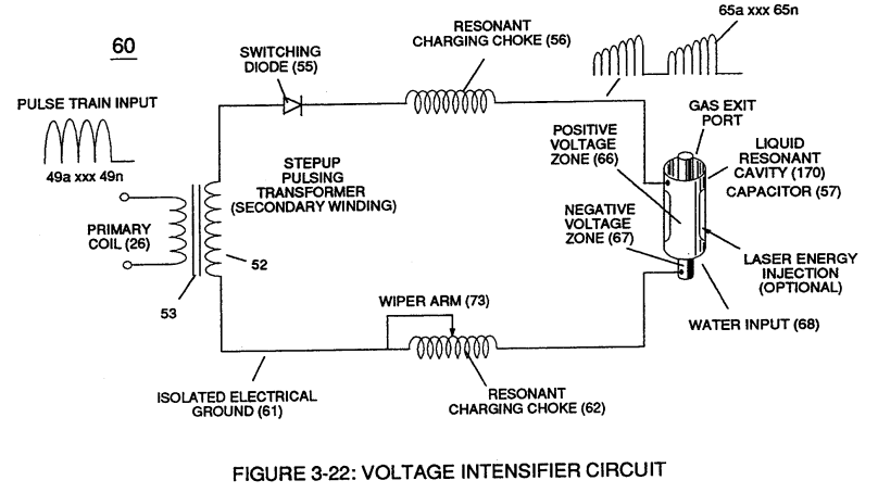
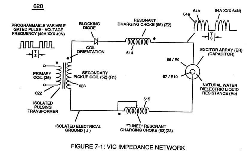
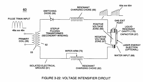
Negative electrical voltage potential (61) of pulse wave (65a xxx 65n) of Figure (3-21) is simultaneously applied to negative voltage zone (67) via Resonant Charging Choke (62) of Figure (3-22) which is electrically linked to opposite end of Primary Coil (26).
How it is written
- (62) 17×
- (56/62) 15× with (56) Resonant Charging Choke
- (52 - 56 - 62) 2× with (52) Secondary Coil, (56) Resonant Charging Choke
- (56/62a xxx 56/62n) 2× with (56) Resonant Charging Choke
- (SS56/62) 2× with (SS56) Resonant Charging Chokes Stages
- (SS56/62a xxx SS56/62n) 1× with (SS56) Resonant Charging Chokes Stages
- (56/62a xx 56/62n + SS56/62a xxx SS56/62n) 1× with (56) Resonant Charging Choke, (SS56) Resonant Charging Chokes Stages
- (56/Z2 – 62/Z3) 1× with (56) Resonant Charging Choke, (Z2) Resonant Choke Coils Electromagnetic Fields Intensity, (Z3) Resonant Choke Coils Electromagnetic Fields Intensity
62a xxx 62n is Meyer's shorthand for a run of the same thing: 62a is the first, 62n the last, and the x's stand for however many lie between. Every stage of the run is this one numeral. A pair before the letters, 583/602a, is a run of two things that go together, one of each per stage.
Drawings 113
-
Figure (3-22) · Analog Voltage generator (40)
-
Figure (3-22) · Voltage Amplitude Control Circuit (50)
-
Figure (3-23) · Voltage Intensifier Circuit (60)
-
Figure (3-22) · Voltage Intensifier Circuit (60)
-
Figure (3-22) · Voltage Dynamics
-
Figure (3-23) · Voltage Dynamics
-
Voltage Intensifier Circuit (60) of Figure (3-22) · Gas Processor
-
(270) of Figure (3-34) · Gas Processor
-
Carries this number · WFC 422DA - Illustrations
-
Carries this number · WFC 422DA - Illustrations
-
Carries this number · WFC 422DA - Illustrations
-
Carries this number · Electronic Circuit Design
-
Carries this number · Electronic Circuit Design
-
Carries this number · Electronic Circuit Design
-
(220) of Figure (18) · Water Fuel Injector (Taper Resonant Cavity Chamber)
-
Carries this number · Water Fuel Injector (Taper Resonant Cavity Chamber)
-
Carries this number · Water Fuel Injector (Taper Resonant Cavity Chamber)
-
The Following Page 1-7 was not available · Water Fuel Injector (Taper Resonant Cavity Chamber)
-
Carries this number · Funneling Effect
-
Figure (4-10) · Water Fuel Injection System - Page 2
-
(270) of (3-34) · In Application of Usage
-
(190) of Figure (3-23) · Tri - Coil Construction
-
Carries this number · VIC Matrix Circuit
-
Voltage Intensifier Circuit (60) of Figure (3-22) · Instant Explosion of Water
-
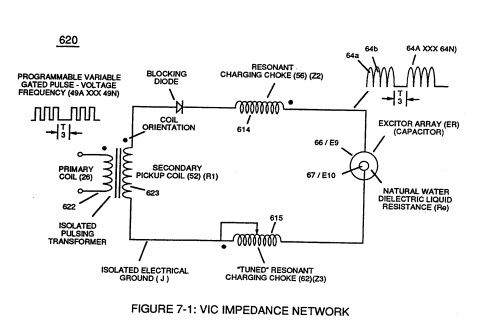
Voltage Intensifier Circuit (620) of Figure (7-1) · Instant Explosion of Water
-
(56/62) of Figure (3-22) · Instant Explosion of Water
-
(T2) of Figure (7-8) · Instant Explosion of Water
-
(56) of Figure (3-22) · Instant Explosion of Water
-
(620) of Figure (7-1) · Instant Explosion of Water
-
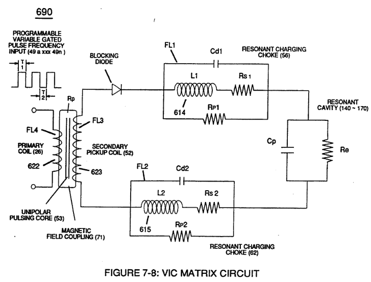
Figure (7-8) · Resistance (Rs)
-
(620) of Figure (7-1) · Resistance (Rs)
-
(690) of Figure (7-8) · Resistance (Rs)
-
Figure (7-13) · Inductance (FL)
-
(614) of Figure (7-1) · Inductance (FL)
-
(580) of Figure (6-1) · Inductance (FL)
-
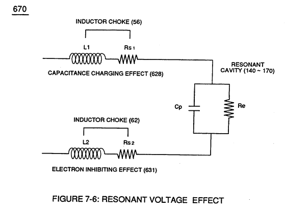
(670) of Figure (7-6) · Inductance (FL)
-
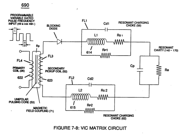
(690) of Figure (7-8) · Inductance (FL)
-
Inductor (614) of Figure (7-1) · Inductance (FL)
-
(614) of (7-1) · Inductance (FL)
-
Figure (7-1) · Capacitance (Cd)
-
(670) of Figure (7-6) · Capacitance (Cd)
-
(670) of Figure (7-6) · Capacitance (Cd)
-
(690) of Figure (7-8) · Capacitance (Cd)
-
(690) of Figure (7-8) · Inductance Reactance (Rs - Cd - FL)
-
Inductance Pulsing-Core (190) of Figure (3-23) · Inductance Reactance (Rs - Cd - FL)
-
Figure (7-8) · Inductance Reactance (Rs - Cd - FL)
-
(620) of Figure (7-1) · Inductance Reactance (Rs - Cd - FL)
-
Carries this number · Taper Resonant Capacitor (ERt)
-
(690) of Figure (7-8) · Taper Resonant Capacitor (ERt)
-
Resonant Capacitor (140 -170) of Figure (7-6) · Capacitance Reactance
-
690 of Figure 7-8 · Circuit Resistance
-
Inductance Charging Effect (660) of Figure (7-5) · Transformer Action
-
Resonant Voltage Effect (670) of Figure (7-6) · Transformer Action
-
Choke-Coil (62) of Figure (7-1) · Transformer Action
-
Carries this number · Electron Bounce Phenomenon
-
(52) of Figure (7-8) · Electron Bounce Phenomenon
-
(see 740 of Figure 7-13) · Voltage Amplitude Switch-Off
-
Carries this number · WFC 426 - Illustrations
-
Carries this number · WFC 426 - Illustrations
-
Carries this number · WFC 426 - Illustrations
-
Carries this number · WFC 426 - Illustrations
-
(690) of Figure (7-8) · 8-2 - Traveling Voltage Wave-Guides
-
(52) of Figure (7-8) · 8-3 - Electrical Voltage-Pulse Wave-Transmission
-
(Cp) of Figure (7-8) · 8-4 - State Space (Sp)
-
(620) of Figure (7-1) · 8-6 - VIC Voltage Sync-Pulse Circuit
-
(690) of Figure (7-8) · 8-6 - VIC Voltage Sync-Pulse Circuit
-
(Cp) of (7-8) · 8-6 - VIC Voltage Sync-Pulse Circuit
-
(850) of Figure (8-11) · 8-6 - VIC Voltage Sync-Pulse Circuit
-
Carries this number · WFC 427 Illustrations
-
Carries this number · WFC 427 Illustrations
-
Carries this number · WFC 427 Illustrations
-
"Resonant Charging Choke" (56) of Figure (7-1) · Propagating Electrical Stress
-
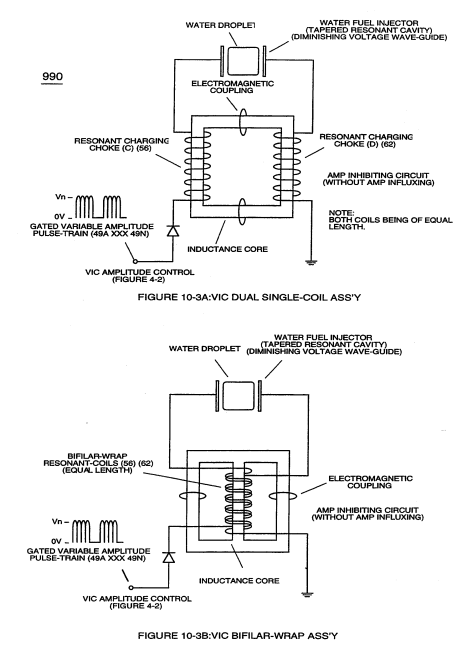
Figure (10-3 A/B) · Propagating Electrical Stress
-
Figure (3-34) · Propagating Electrical Stress
-
Voltage Intensifier Circuit (60) of Figure (3-22) · Propagating Electrical Stress
-
(990) of Figure (10-3) · Propagating Electrical Stress
-
(60) of Figure (3-22) · Propagating Electrical Stress
-
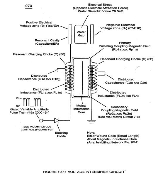
The programmable pulse-frequency (49a xxx 49n) of Figure (10-1) input is simply adjusted to tune-in to the dielectric property of the Water Molecule. · Propagating Electrical Stress
-
Carries this number · Voltage to Amp Differential Ratio
-
blocking diode (55) of Figure (3-34) · Voltage to Amp Differential Ratio
-
Figure (10-3A) · Voltage to Amp Differential Ratio
-
(620) of figure (7-1) · Voltage to Amp Differential Ratio
-
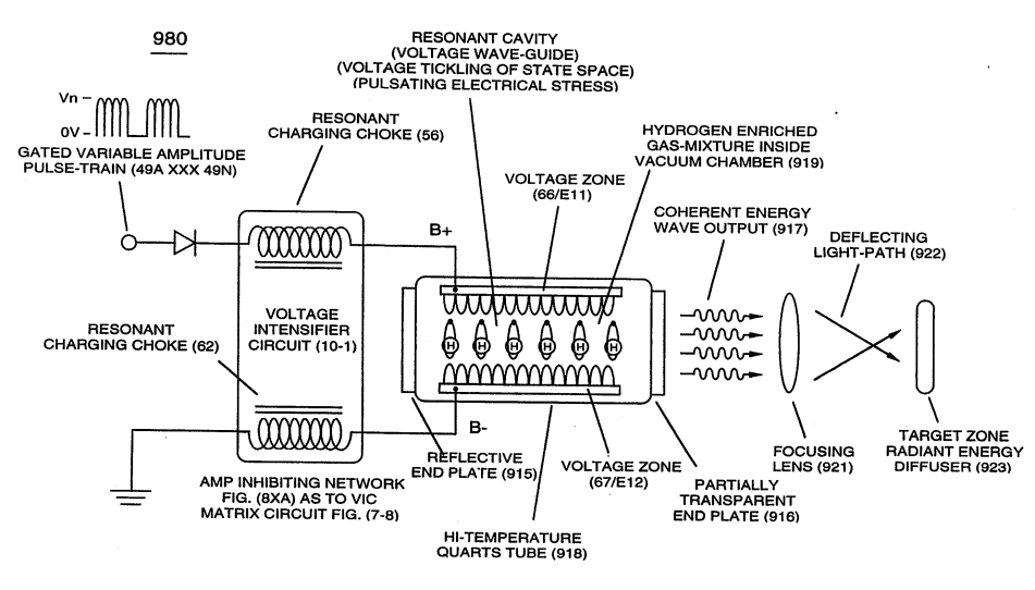
... emitting Coherent Energy Wave-Form (917), as so illustrated in (980) of Figure (10-2). · Optical Thermal Lens
-
Carries this number · WFC 429 - Illustrations
-
Carries this number · WFC 429 - Illustrations
-
Carries this number · WFC 429 - Illustrations
-
Carries this number · WFC 429 - Illustrations
-
Carries this number · WFC 429 - Illustrations
-
Carries this number · Wobbling Effect
-
dual unipolar voltage pulse circuit (1010) of Figure (11-1) · Voltage Flexing Process
-
(1030) of figure (11-3) · Voltage Flexing Process
-
voltage intensifier circuit (990) of Figure (10-3) · VIC Switchover Circuit
-
(970) of Figure (10-1) · VIC Switchover Circuit
-
Differential Voltage Wave-Guild (1040B) · Electrical Crossover Switching Circuit
-
When (B+/B+ - B-/B- / 1030B) switch function is activated, switch terminals (T1/T2 - T3/T4) are closed. · Electrical Crossover Switching Circuit
-
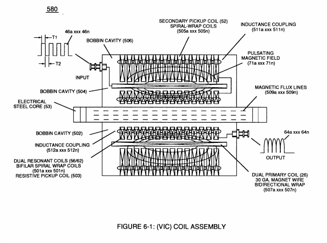
coil-structures (580) of Figure (6-1) · Voltage Intensifier Coil-Assembly
-
(700) of Figure (7-9) · Instant Explosion of Water
-
(FI) of Figure (7-3b) · Instant Explosion of Water
-
Figure (7-3) · Inductance (FL)
-
(640) of Figure (7-3) · Capacitance (Cd)
-
"Electron Bounce" phenomenon (700) of Figure (7-9) · Inductance Reactance (Rs - Cd - FL)
-
Figure (7-3) · Multi-layer Coil
-
(580) of Figure (6-1) · Multi-layer Coil
-
"Electron Clustering" (Grouping/collecting negative charged particles at a given point) (700) of Figure (7-9) · Transformer Action
-
Distributed Capacitance (Cda xxx Cdn) of Figure (7-3) · Electron Bounce Phenomenon
-
(700) of Figure (7-9) · Electron Bounce Phenomenon
-
The figure it sits on · WFC 426 - Illustrations
-
(580) of Figure (6-1) (WFC memo 425) · 8-2 - Traveling Voltage Wave-Guides
-
(631) of Figure (7-9) · 8-3 - Electrical Voltage-Pulse Wave-Transmission
-
(690) of Figure (7-8) · Propagating Electrical Stress
-
"bifilar" wrapped coils (Figure 7-3) · Propagating Electrical Stress
-
(580) of Figure (6-1) · Voltage to Amp Differential Ratio
-
The figure it sits on · VIC Switchover Circuit
Where it is named · 46
Voltage Intensifier Circuit (60) 6×
-
Resonant Charging Choke (62)
Negative electrical voltage potential (61) of pulse wave (65a xxx 65n) of Figure (3-21) is simultaneously applied to negative voltage zone (67) via Resonant Charging Choke (62) of Figure (3-22) which is electrically linked to opposite end of Primary Coil (26).
-
variable resonant charging choke (62)
The resultant signal coupling ( 65a xx 65n ) of Figure (3-21) is accomplished since primary coil (26), pulsing core (53), secondary coil (52), switching diode (55), resonant charging choke (56), resonant cavity assembly (170), natural water (68), and variable resonant charging choke (62) forms Voltage Intensifier Circuit (60) of Figure (3-22), as illustrated in Figure (3-22) as to Figure (3-23).
-
Variable inductor-coil (62)
Variable inductor-coil (62) of Figure (3-22), similar to inductor (56) connected to opposite polarity voltage zone (67) further inhibits electron movement or deflection within voltage intensifier circuit (60).
-
Inductor (62)
Inductor (62) in relationship to inductor (56) electrically balances the opposite electrical potential across voltage zone (66/67).
-
resonant charging chokes (56/62)
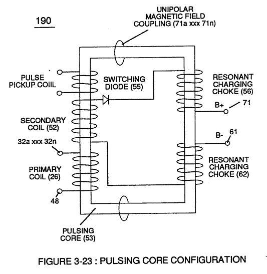
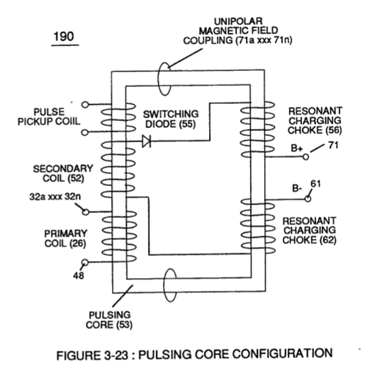
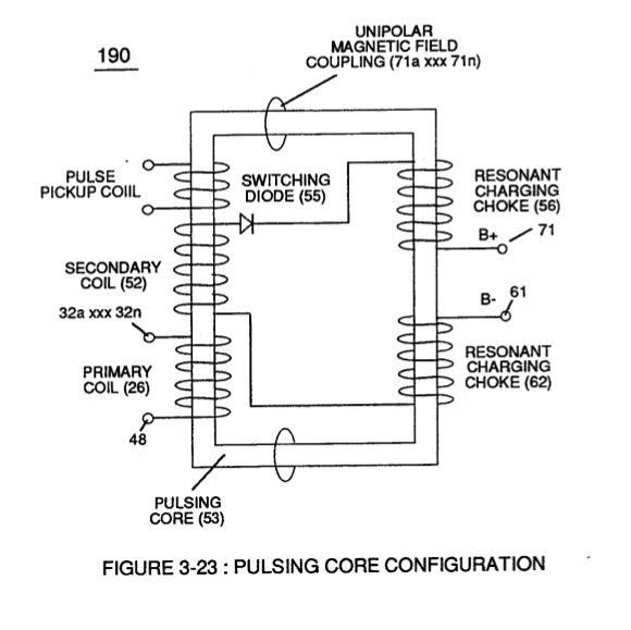
Amp restriction beyond "resonant action" occurs when unipolar magnetic field coupling (71) of Figure (3-23) is allowed to simultaneously drop (pulsating magnetic field) across both resonant charging chokes (56/62) during pulsing operations since electron mass is an electromagnetic entity which is subject to inductor fields (56/62) produced by pulsating magnetic field (71a xxx 71n) of Figure (3-23).
-
subject to inductor fields (56/62)
Amp restriction beyond "resonant action" occurs when unipolar magnetic field coupling (71) of Figure (3-23) is allowed to simultaneously drop (pulsating magnetic field) across both resonant charging chokes (56/62) during pulsing operations since electron mass is an electromagnetic entity which is subject to inductor fields (56/62) produced by pulsating magnetic field (71a xxx 71n) of Figure (3-23).
Water Fuel Injector (Taper Resonant Cavity Chamber) 3×
-
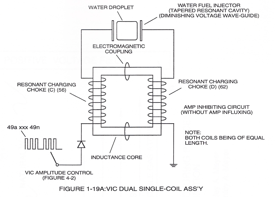
… Together, the resistive valve of Stainless Steel wire-coil (56/57) and its inductance generated electromagnetic field (62) of Figure (19) opposes the movement of electrons since the dielectric valve of wire-coils (56/57) inhibits electron exchange while the generated inductance field (62) locks onto the electromagnetic field of the electrons ...generated coil inductance field (62) being greater in electromagnetic... …
-
… Together, the resistive valve of Stainless Steel wire-coil (56/57) and its inductance generated electromagnetic field (62) of Figure (19) opposes the movement of electrons since the dielectric valve of wire-coils (56/57) inhibits electron exchange while the generated inductance field (62) locks onto the electromagnetic field of the electrons ...generated coil inductance field (62) being greater in electromagnetic... [ends abruptly...]
-
… he dielectric valve of wire-coils (56/57) inhibits electron exchange while the generated inductance field (62) locks onto the electromagnetic field of the electrons ...generated coil inductance field (62) being greater in electromagnetic... [ends abruptly...]
Tri - Coil Construction 1×
-
Resonant Choke Coils (56/62)
Resonant Choke Coils (56/62) of Figure (3-23) (Memo WFC 422 DA) are composed of 430F or 430FR inductance stainless steel film coated (hi dielectric value) wire (typically .004 Ga. …
Instant Explosion of Water 2×
-
Resonant Charging Chokes (56/62)
VIC voltage circuit (60) utilizes copper wire-wrap to form Resonant Charging Chokes (56/62) of Figure (3-22) in conjunction with Switching Diode (55) to encourage and make use of "Electron Bounce" phenomena (700) of Figure (7-9) to help promote Step Charging Effect (628) of Figure (7-7) by …
-
(56/62) of Figure (3-22)
Inductance Reactance (Rs - Cd - FL) 1×
-
Inductor Chokes (56/62)
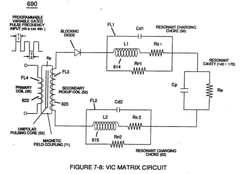
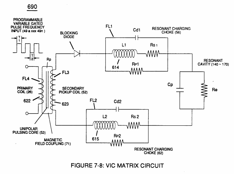
… to VIC Coil Assembly (580) of Figure (6-1) enters into and passes through both Inductors (L1/L2) simultaneously and offers not only further electron-flow restriction (Rp1/Rp2) to both Inductor Chokes (56/62) but automatically increases voltage potential (xxx V g xxx Vh xxx Vn) of opposite voltage intensity of equal magnitude (66/67) across Resonant Cavity (140 -170)
Circuit Resistance 2×
-
(Z3) is determined by inductance field strength (FL2) and resistive value (RS2) (typically 11.6KQ) of stainless steel (sls) wire-coil (62) (L2) when being exposed to the same external magnetic coupling field strength (Rp)
-
... each choke-coil (LIIL2) being of the same impedance value since both coil-wraps (56/62) are Bifilar wound together onto a single spool-bobbin, (Re) is the dielectric property of water and it's resistive value is typically (78.54 Q) since "rain water" (85f) contains less than 20ppm of any type of contaminates due to Water Evaporation Process (530) of Figure (5-6).
Transformer Action 5×
-
(L1) and (L2) are the inductances of each individual choke coil (56)(62) in series with Secondary Coil (52) Electrical Voltage Potential (700) of Figure (7-9) and being exposed to the same Voltage Transformer (26 - 53 - 52) magnetic field (Rp) with aiding fields,
-
Inductor Coils (26 - 52 - 56 - 62)
VIC Coil Assembly (580) of Figure (6-1) as to (690) of Figure (7-8) in reference to Schematic Circuit (620) of Figure (7-1) is constructed in such a way as to rotate and position Inductor Coils (26 - 52 - 56 - 62) to be of the same electromagnetic polarity orientation, indicator mark (e)
-
Choke-Coil (62)
… given point) (700) of Figure (7-9) to produce ''Negative Voltage Potential" ( B- ) at one side of Water Gap (Cp) of Figure (7-8) is accomplished by low electrical power input (Tab 38) when Choke-Coil (62) of Figure (7-1) magnetic field (FL2) (690) of Figure (7-8) during pulse on-time (49) impede "Electron-Flow" since electron mass is composed of electromagnetic matter which interacts with magnetic fie …
-
Choke-Coils (56/62)
... producing "Electrical Stress" (SS' - RR') (B+/B-) across Water Gap (Cp) since both Choke-Coils (56/62) conduct voltage potential (Negative or Positive) during pulsing operations.
Electron Bounce Phenomenon 5×
-
… Vn) (SS' - 617 -RR') is accomplished when magnetic flux lines of force (71a xx 71n) (Rp) emanating away from closed-loop magnetic pulsing core (53) of Figure (190) penetrates Inductance coil-windings (52 - 56 - 62) simultaneously during each and every pulse on-time (T1a xxx T1n) as programmable pulse-train (49a xxx 49n T3 - 49a xxx 49n) is adjusted to "Tune - in" to the dielectric property of Water (Re)
-
inductance coils (52 - 56 - 62)
.... causing mutual inductance (μ1) (see equations Eq 28 thru Eq 30) to transform Distributed Capacitance (Cda xxx Cdn) of Figure (7-3) of each inductance coils (52 - 56 - 62) into a coherent Voltage Potential (Yo •..• Vn) equaling the sum of Voltage Potential (Vp) developed across each Pickup Coils (VpT + Vp1 + Vp2)
-
… ) of Figure (7-8) is further expressed in the following equation: Where, (Lt cc) is the total inductance of Choke Coils (FL1 - FL2), (L1) and (L2) are the inductance of each individual choke coil (56)(62) in series with Secondary Coil (52) Electrical Voltage Potential (700) of Figure (7-9) and being exposed to the same Voltage Transformer (26 - 53 - 52) magnetic field (Rp) with aiding fields, (M) is t …
-
choke coil (62)
whereas, the "Liberated" negative electrical charged electrons (641a xxx 641n) added together provides Negative Voltage Potential (631) to the opposite end of Secondary Wire (52) being electrically connected to choke coil (62).
-
Choke Coil (62)
Sustaining and maintaining the resultant induced Voltage Potential (Vo - Vn) without "Electron Discharged" (inhibiting electron flow) through Choke Coil (62) while, at the same time, inhibiting (preventing) any additional or other electrons from entering into Secondary copper wire-zone (52) by way of Choke Coil (56) is herein called "Electron Bounce Phenomenon" (EbP), as illustrated in (700) of Figure (7-9).
8-3 - Electrical Voltage-Pulse Wave-Transmission 2×
-
Resonant Charging Chokes (56/Z2 – 62/Z3)
The newly established leading voltage edge (Vpa) and trailing voltage edge (Vpb) being uniform in shape/configuration since both Resonant Charging Chokes (56/Z2 – 62/Z3) resistive values are the same (Typically 11.6 kΩ each) and incoming signal (49a xxx 49n) is electrically linked with Water-Gap Capacitor (Cp) of Figure (7-8) having dielectric liquid of Water (85) there between.
-
Resonant Charging Chokes (56/62)
… Remember, Secondary Voltage pickup coil (52) of Figure (7-8) displaces and separates Resonant Charging Chokes (56/62) on opposite end of said Secondary Pickup Coil (52).
Propagating Electrical Stress 4×
-
Resonant Charging Choke (62)
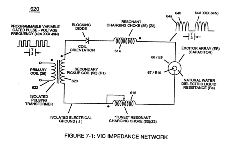
The energized "Resonant Charging Choke" (56) of Figure (7-1) as to Figure (10-1) by way of input voltage-pulses (49a xxx 49n) creates an electromagnetic coupling field (Rp1) of Figure (7-8) due to its self-inductance (640) of Figure 7-3B) crosses over and passes through electrically ground connected Resonant Charging Choke (62), as so illustrated in Figure (10-1)
-
secondary coil (62)
... forming "Mutual Inductance Fields" (Rp1/Rp2) once secondary coil (62) is electromagnetically energized by primary coil (56) and vice versa
-
… The length and diameter size of the copper-wire spiral wrapped coil (56/62) of Figure (10-1) being paired together and electrically energized in conjunction with applied Voltage Pulse-Frequency determines how much "Amp Leakage" will occur across capacitor Gap (Cp) while "Vol …
-
Resonant Charging Chokes (56/62)
To reduce amp leakage still further, the copper wire of both Resonant Charging Chokes (56/62) can be replaced with a magnetically inductive stainless steel wire (430F/FR) having a resistive value (Ohms) to the flow of electrons while taking on the capacitance and inductance characteristic of a coil wire.
Voltage to Amp Differential Ratio 11×
-
Resonant Charging Chokes Stages (56/62a xx 56/62n + SS56/62a xxx SS56/62n)
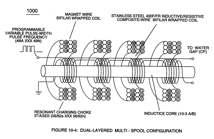
… Figure (8-1) is simply produced when Programmable Variable Pulse-Width Pulse-Train Waveform (49a xxx 49n) is allowed to be electrically transmitted through and beyond Resonant Charging Chokes Stages (56/62a xx 56/62n + SS56/62a xxx SS56/62n) of Figure (10-4) that are not only electrically connected in sequential order but likewise magnetically linked by Inductance Coupling field (511/512a xxx 511/512n), as so pictorially illustrated in ( …
-
… etc.) of Figure (10-4) in "Sequential Order" (-S-) since the total number of Multi-Coil Magnet bifilar coils (56/62a xxx 56/62n) serially electrically connected together are sequentially electrically linked to an equal number of serially electrically aligned Stainless Steel Resonant Coils (SS/56/62a xxx SS/56/62n)
-
bifilar coil assembly (56/62a xxx 56/62n -S- SS56/62a xxx SS56/62n)
... allowing each/both bifilar coil assembly (56/62a xxx 56/62n -S- SS56/62a xxx SS56/62n) to be electrically and magnetically energized in the same progressive direction toward Water Gap (Cp) and away from blocking diode (55) of Figure (3-34) as to Figure (10-1) and Figure (10-3)
-
Coil-Stage Assembly (SS56/62a xxx SS56/62n)
Stainless Steel bifilarCoil-Stage Assembly (SS56/62a xxx SS56/62n) is electrically placed between Magnet Coil-Stage Assembly (56/62a xxx 56/62n) and Water Gap (Cp) to obtain optimum Voltage to Amp Differential Ratio (Vhighest:Alowest ratio).
-
Magnet Coil-Stage Assembly (56/62a xxx 56/62n)
Stainless Steel bifilarCoil-Stage Assembly (SS56/62a xxx SS56/62n) is electrically placed between Magnet Coil-Stage Assembly (56/62a xxx 56/62n) and Water Gap (Cp) to obtain optimum Voltage to Amp Differential Ratio (Vhighest:Alowest ratio).
-
Coil Stages (56/62a xxx 56/62n + SS56/62a xxx SS56/62)
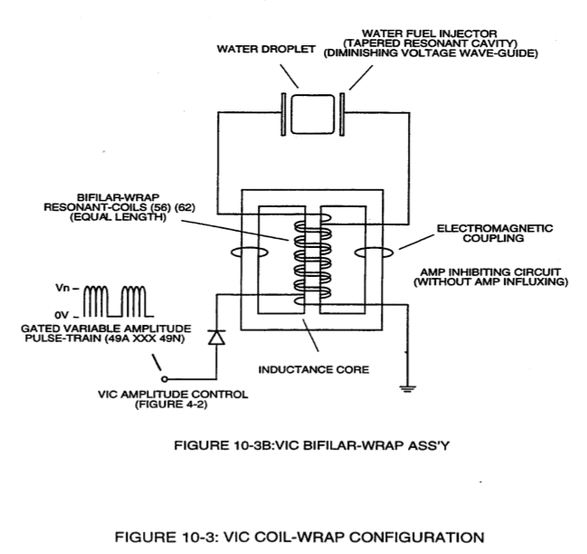
Together, Coil Stages (56/62a xxx 56/62n + SS56/62a xxx SS56/62) added/stacked sequentially into a single overall coil-array assembly (990A/B) of Figure (10-3) forms Amp Inhibiting Network (Figure 8XA) as to (970) of Figure (10-1) (hereinafter called VIC Multi-Coil Spool Assembly).
-
Coil-Wire (56/62)
The magnet Coil-Wire (56/62) is best suited for Voltage inducement while the inductance/capacitance/resistance properties of Stainless Steel coil-wire (SS56-SS62) is appropriately used to restrict electron movement beyond the self-inductance of each energized coil when elevated voltage levels (up to beyond 40 kilovolts) are to be reached/obtained without experiencing any appreciable amount of "Amp Influxing."
-
Generally, magnet coil-wire length is longer than the Stainless steel coil-wire length and magnet bifilar-coil (56/62) is placed on top of Stainless Steel bifilar-coil (SS56/62) to maximize mutual inductance coil-field (Rp2) (adding Rp1+Rp2) of (690) of Figure (7-8) to cause coil capacitance (Cda xxx Cdn) to help maintain and even increase pulse voltage amplitude (xxx Vn + Vn 1 + Vn2 + Vn .... …
-
Stainless Steel bifilar-coil (SS56/62)
Generally, magnet coil-wire length is longer than the Stainless steel coil-wire length and magnet bifilar-coil (56/62) is placed on top of Stainless Steel bifilar-coil (SS56/62) to maximize mutual inductance coil-field (Rp2) (adding Rp1+Rp2) of (690) of Figure (7-8) to cause coil capacitance (Cda xxx Cdn) to help maintain and even increase pulse voltage amplitude (xxx Vn + Vn 1 + Vn2 + Vn .... …
-
SS Coil-Wire (SS56/62)
… etc.) while the resistive value (Rs2) of SS Coil-Wire (SS56/62) performs the work of further resisting the flow of amps not inhibited by both self-Inductance fields (Rpl + Rp2), as so illustrated in (690) of Figure (7-8).
-
In all cases, bifilar coils (56/62 - SS56/62) are electromagnetically orientated in the same direction.
Optical Thermal Lens 1×
-
... forming Capacitor Gap (Cv) since the gas medium, so exhibits a dielectric value and amp in-fluxing (prohibiting amp leakage into and away from Capacitor Vacuum-Gap (Cv)) is held to a minimum due to the bifilar wrapped resonant-coils (56/62).
VIC Switchover Circuit 1×
-
The simultaneous formation of both the positive voltage field (952) and the negative voltage field (953) is simply accomplished by the mutual electromagnetic inductance coupling field that is produced between the two bifilar wrapped coils (957/56 - 958/62) when the primary coil (957/56) is electrically energized by incoming voltage pulse train (T4a xxx T4n), as so illustrated in (970) of Figure (10-1).
Appendix B - Glossary of Applicaiton Notes 2×
-
Choke-Coil (62)
… a given point) (700) of Figure (7-9) to produce "Negative Voltage Potential" (B-) at one side of Water Gap (Cp) of Figure (7-8) is accomplished by low electrical power input (Tab 38) when Choke-Coil (62) of Figure (7-1) magnetic field (FL2) (690) of Figure (7-8) during pulse on-time (49) impede "Electron-Flow" since electron mass is composed of electromagnetic matter which interacts with magnetic field strength (FL2). …
-
Choke-Coils (56/62)
… producing "Electrical Stress" (SS' - RR') (B+/B-) across Water Gap (Cp) since both Choke-Coils (56/62) conducts voltage potential (Negative or Positive) during pulsing operations.