Figure (3-15)
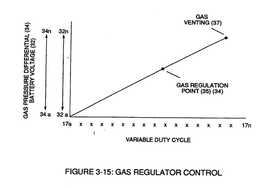
Gas Regulator Control
Also written VIC Mount Plate
How it is written
- (3-15) 11×
Drawings 3
-
Figure (3-15) · Voltage Amplitude Control Circuit (50)
-
Captioned as this figure · WFC 422DA - Illustrations
-
3-15 VIC Mount Plate · Voltage Intensifier Coil Assembly
On this figure 4
Where it is named · 11
Voltage Amplitude Control Circuit (50) 7×
-
Regulator stage (27) of circuit (50) converts battery voltage potential (29) of Figure (3-6) via electrical terminal (31) of Figure (3-5) as to Figure (3-6) into a analog voltage signal (32) of Figure (3-15) which corresponds to but is electrically isolated (crossover voltage from two separate power supplies) from incoming gas volume signal (23) of Figure (3-14), as shown in Figure (35).
-
Second regulator stage (28) simply acts and function as a gas regulator (33) by preventing Fuel Gas production beyond a predetermined gas pressure level (34) of Figure (3-15) during Fuel Cell operations and, as such, maintains constant gas pressure to Fuel Injectors (36) of Figure (3-1) regardless of engine performance (R.P.M. response).
-
If gas pressure (34a xx) should exceed gas point (35) during injector off-time, gas pressure release valve (75) of Figure (3-24) (gas venting 37 of Figure 3-15) expels Fuel gases (88) until gas point (34) is either reached or a delay timing circuit activates Safety Control Circuit (14) of Figure (3-6) which, in turns, switches off or disconnects applied ele …
-
Figure (3-15)
Voltage Intensifier Circuit (60) 4×
-
By integrating and joining together variable voltage amplitude control signal (318 xxx 32n) of Figure (3-15) with variable controlled switch-gate (49a xxx 49n) of Figure (3-18) across primary coil (26) of Figure (3-22),
-
Figure (3-15)
-
Analog voltage signal (32a xxx 32n) of Figure (3-15) allows pulse train (51a xxx 51n) voltage amplitude (V0 xxx Vn) of Figure (3-19) to vary from one up to twelve volts (battery supply 28 of Figure 3-6 by attenuating Laser Accelerator circuit (10) of Figure (3-5) via Hydrogen Gas Control Circuit (100).
-
Figure (3-15)