Figure (3-18)
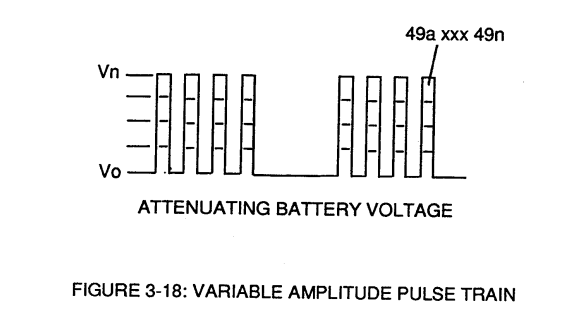
Variable Amplitude Pulse Train
How it is written
- (3-18) 8×
Drawings 2
-
Figure (3-18) · Cell Driver Circuit (90)
-
Captioned as this figure · WFC 422DA - Illustrations
On this figure 5
Where it is named · 8
Cell Driver Circuit (90) 2×
-
Figure (3-18)
-
The resultant pulse wave form (49a xxx 49n) of Figure (3-18) superimposed onto primary coil (26) is exact duplicate of proportional pulse train (47a xxx 47n).
Voltage Intensifier Circuit (60) 6×
-
By integrating and joining together variable voltage amplitude control signal (318 xxx 32n) of Figure (3-15) with variable controlled switch-gate (49a xxx 49n) of Figure (3-18) across primary coil (26) of Figure (3-22),
-
Figure (3-18)
-
The established resonant frequency is, of course, independent of voltage amplitude, as illustrated in Figure (3-21) as to Figure (3-18).
-
Figure (3-18)
-
Figure (3-18)