(65) · also written as a run, 65a xxx 65n
Voltage Potential
Also written pulse voltage potential · voltage intensity · voltage stimulation · applied voltage · voltage · pulsating high intensity voltage field · Resonant Charging pulse train · step-charging voltage-wave and 7 more
Where it is first named
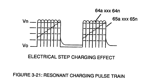
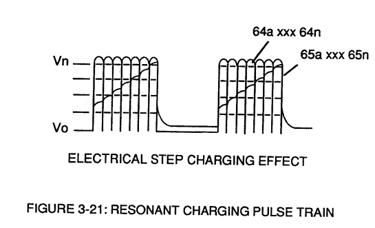
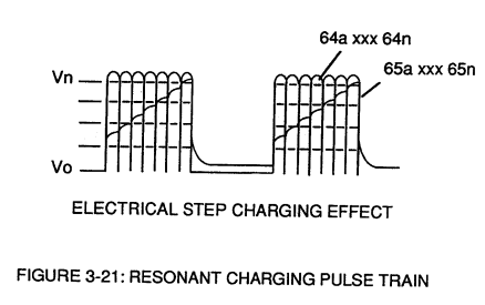
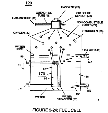
These controlled and variable pulse features are, now, translated to Resonant Charging pulse train (65a xxx 65n) of Figure (3-21) via Unipolar pulse train (64a xxx 64n) of Figure (3-20) during Resonant Action (160) of Figure (3-26) when signal coupling is applied across Resonant Cavity (170) of Figure (3-24) via positive voltage zone (66).
How it is written
- (65) 11×
- (65a xxx 65n) 10×
- (65a xx 65n) 2×
65a xxx 65n is Meyer's shorthand for a run of the same thing: 65a is the first, 65n the last, and the x's stand for however many lie between. Every stage of the run is this one numeral.
Drawings 63
-
Stanley A. Meyer Page17 of 28 · WFC 417 — WFC 417
-
Figure (3-22) · Analog Voltage generator (40)
-
Figure (3-21) · Voltage Amplitude Control Circuit (50)
-
Figure (3-22) · Voltage Amplitude Control Circuit (50)
-
Figure (3-21) · Voltage Intensifier Circuit (60)
-
Figure (3-22) · Voltage Intensifier Circuit (60)
-
Carries this number · Voltage Dynamics
-
Figure (3-22) · Voltage Dynamics
-
In both cases, electrical charge deflection or movement is directly related to applied voltage (65). · Voltage Dynamics
-
Voltage Intensifier Circuit (60) of Figure (3-22) · Gas Processor
-
Carries this number · Gas Processor
-
(270) of Figure (3-34) · Gas Processor
-
Carries this number · WFC 422DA - Illustrations
-
Carries this number · WFC 422DA - Illustrations
-
Carries this number · WFC 422DA - Illustrations
-
3-5 Outer Core Bobbin · Voltage Intensifier Coil Assembly
-
3-8 Multi-Coil Spool · Voltage Intensifier Coil Assembly
-
Carries this number · Electronic Circuit Design
-
Carries this number · Electronic Circuit Design
-
Electron Ejection Process (230) of Figure (29) · Water Fuel Injector (Taper Resonant Cavity Chamber)
-
(270) of (3-34) · In Application of Usage
-
Voltage Intensifier Circuit (60) of Figure (3-22) · Instant Explosion of Water
-
(56/62) of Figure (3-22) · Instant Explosion of Water
-
(56) of Figure (3-22) · Instant Explosion of Water
-
Carries this number · 8-6 - VIC Voltage Sync-Pulse Circuit
-
Carries this number · 8-6 - VIC Voltage Sync-Pulse Circuit
-
Figure (3-34) · Propagating Electrical Stress
-
Voltage Intensifier Circuit (60) of Figure (3-22) · Propagating Electrical Stress
-
(60) of Figure (3-22) · Propagating Electrical Stress
-
blocking diode (55) of Figure (3-34) · Voltage to Amp Differential Ratio
-
Figure (3-24) · Voltage Amplitude Control Circuit (50)
-
Figure (3-26) · Voltage Intensifier Circuit (60)
-
Figure (3-23) · Voltage Intensifier Circuit (60)
-
Figure (3-27) · Voltage Intensifier Circuit (60)
-
Figure (3-23) · Voltage Dynamics
-
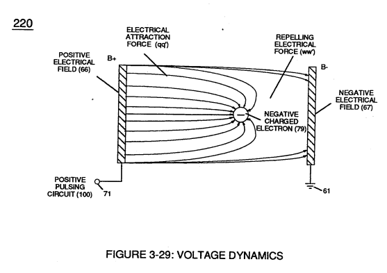
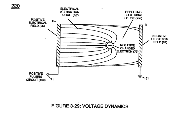
Ions or particle mass having the same or like electrical charges will move away from one another, as illustrated in (220) of Figure (3-29). · Voltage Dynamics
-
Figure (3-29) · Electrically Charged Water Molecule
-
The figure it sits on · Electrically Charged Water Molecule
-
Figure (3-26) · Electrically Charged Water Molecule
-
Figure (3-24) · Electrical Polarization process
-
Fuel Cell (120) of Figure (3-24) · Operational Parameters
-
The figure it sits on · WFC 422DA - Illustrations
-
The figure it sits on · WFC 422DA - Illustrations
-
The figure it sits on · WFC 422DA - Illustrations
-
The figure it sits on · WFC 422DA - Illustrations
-
The figure it sits on · WFC 422DA - Illustrations
-
Figure (25) · Water Fuel Injector (Taper Resonant Cavity Chamber)
-
Figure (29) · Water Fuel Injector (Taper Resonant Cavity Chamber)
-
(160) of Figure (3-26) · Water Fuel Injection System - Page 1
-
(85) of Figure (3-26) · In Application of Usage
-
(160) of Figure (3-26) · In Application of Usage
-
(210) of Figure (3-27) (Memo WFC 422DA) · Covalent Switch-Off
-
(190) of Figure (3-23) · Tri - Coil Construction
-
(85) of Figure (3-26) · Resistance (Rs)
-
(210) of Figure (3-27) · Inductance (FL)
-
Figure (3-24) · Inductance (FL)
-
Inductance Pulsing-Core (190) of Figure (3-23) · Inductance Reactance (Rs - Cd - FL)
-
The figure it sits on · Electron Bounce Phenomenon
-
Voltage Dynamics (220) of Figure (3-29) · Electron Bounce Phenomenon
-
(210) of Figure (3-27) · Electrovalent Bonding
-
The figure it sits on · WFC Exhaust Air Reclaimer
-
Voltage Dynamics (220) of Figure (3-29) · WFC Exhaust Air Reclaimer
-
(160) of Figure (3-26) · Propagating Electrical Stress
Where it is named · 23
Voltage Intensifier Circuit (60) 4×
-
Resonant Charging pulse train (65a xxx 65n)
These controlled and variable pulse features are, now, translated to Resonant Charging pulse train (65a xxx 65n) of Figure (3-21) via Unipolar pulse train (64a xxx 64n) of Figure (3-20) during Resonant Action (160) of Figure (3-26) when signal coupling is applied across Resonant Cavity (170) of Figure (3-24) via positive voltage zone (66).
-
pulse wave (65a xxx 65n)
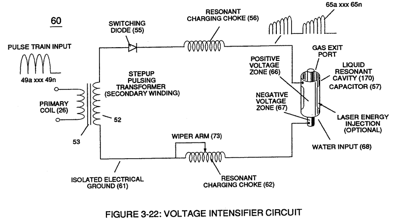
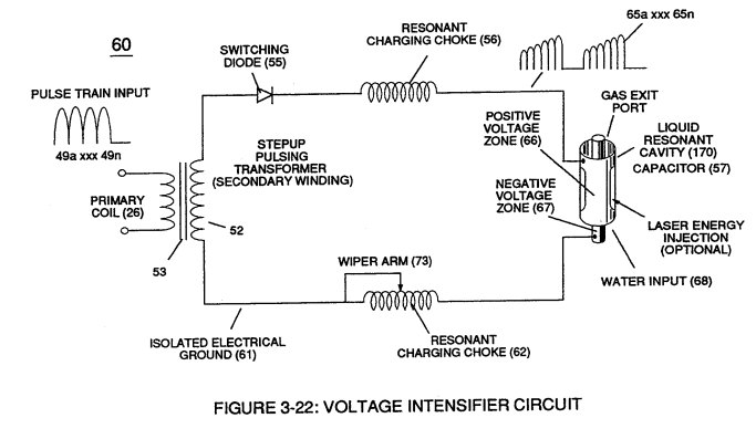
Negative electrical voltage potential (61) of pulse wave (65a xxx 65n) of Figure (3-21) is simultaneously applied to negative voltage zone (67) via Resonant Charging Choke (62) of Figure (3-22) which is electrically linked to opposite end of Primary Coil (26).
-
signal coupling (65a xx 65n)
The resultant signal coupling ( 65a xx 65n ) of Figure (3-21) is accomplished since primary coil (26), pulsing core (53), secondary coil (52), switching diode (55), resonant charging choke (56), resonant cavity assembly (170), natural water (68), and variable resonant charging choke (62) forms Voltage Intensifier Circuit (60) of Figure (3-22), as illustrated in Figure (3-22) as to Figure (3-23).
-
pulsating high intensity voltage field (65a xxx 65n)
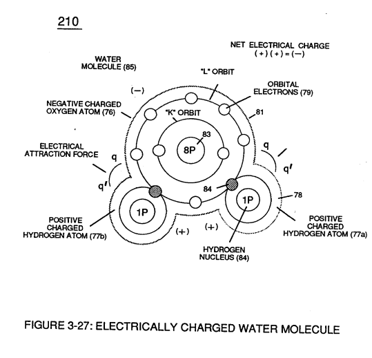
The resultant interfacing voltage circuit (190), now, exposes water molecule (210) of Figure (3-27) to a pulsating high intensity voltage field (65a xxx 65n) of opposite polarity (66/67) while restricting amp flow within circuit (60) of Figure (3-22).
Voltage Dynamics 3×
-
voltage potential (65a xxx 65n)
Voltage is "electrical pressure" or "electrical force" within electrical circuit (60) and is known as voltage potential (65a xxx 65n) of Figure (3-21).
-
Voltage potential (65)
Voltage potential (65) is an "unaltered" or "unchanged" energy-state when "electron movement" or "electron deflection" is prevented or restricted within electrical circuit (190) of Figure (3-23).
-
applied voltage (65)
In both cases, electrical charge deflection or movement is directly related to applied voltage (65).
Electrically Charged Water Molecule 1×
-
Voltage potential (65)
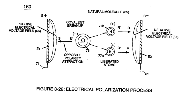
Voltage potential (65) within electrical circuit (60) can cause one or more electrons (79) to be dislodged from the water molecule atom (85) of Figure (3-26) due to opposite electrical polarity attraction (qq') of Figure (3-29) between unlike charged entities, as shown in (160) of Figure (326) as to Newton's and Coulomb's laws of electrical-force.
Electrical Polarization process 5×
-
pulse voltage potential (65)
Placement of a pulse voltage potential (65) across Excitor plates (E1/E2) (voltage zones 66/67) of Figure (3-29) as to Figure (3-26) while inhibiting and preventing electron flow within voltage intensifier circuit (190) of Figure (3-23) causes …
-
step-charging voltage-wave (65)
… ical attraction force (RR') causes positive charged hydrogen atoms (77a/b) to migrate in the opposite direction to negative voltage-plate (E2) (negative voltage zone 67) as step-charging voltage-wave (65) increases in voltage amplitude from several millivolts to several hundred volts during each pulse train (65a xxx 65n) which, in application, causes water molecule (210) of Figure (3-27) charged atoms …
-
during each pulse train (65a xxx 65n)
… on to negative voltage-plate (E2) (negative voltage zone 67) as step-charging voltage-wave (65) increases in voltage amplitude from several millivolts to several hundred volts during each pulse train (65a xxx 65n) which, in application, causes water molecule (210) of Figure (3-27) charged atoms (76/77) to elongate (increasing distance between unlike atoms 76/77) to the point where covalent hydrogen electrons ( …
-
voltage pulse (65a xxx 65n)
Repetitive duplication of voltage pulse (65a xxx 65n) continues to separate or split apart other water molecules (85a xxx 85n) which, in turns, forms hydrogen (86) and oxygen (87) gas-mixture (88) of Figure (3-24).
-
voltage stimulation (65)
Dissociation of water molecule (85) by way of voltage stimulation (65) is herein called "The Electrical Polarization Process", as illustrated in (160) of Figure (3-26).
Resonant Action 5×
-
voltage amplitude (65)
Applied electrical attraction force (TT') and (UU') always being of equal voltage intensity but opposite in electrical polarity as voltage amplitude (65) is attenuated.
-
pulse-width (65a xxx 65n)
By attenuating voltage amplitude (Vo xxx Yn) in conjunction with pulse-width (65a xxx 65n) allows voltage intensifier circuit (190) of Figure (3-23) to tune-in and match the resonant characteristics or resonant frequency of water bath (91) since water bath (91) always maintains its dielectric properties during pulsing operations.
-
... stabilizing gas production during voltage stimulation (65), as shown in (120) of Figure (3-24).
-
voltage stimulation (65)
In terms of Longevity, voltage zones (E1/E2) are composed of or made of stainless steel T304 material which is chemically inert to hydrogen, oxygen, and ambient air gases (dissolved gases in water) being liberated from water bath (68) during voltage stimulation (65).
-
voltage (65)
Under actual certified laboratory testing stainless steel T304 life expectancy (material decomposition) is .0001 per year since voltage (65) is a physical force, setting up a non-chemical environment since amps consumption is being restricted to a minimum and "no" electrolyte is added to water bath (68).
Gas Processor 5×
-
voltage intensity (65a xxx 65n)
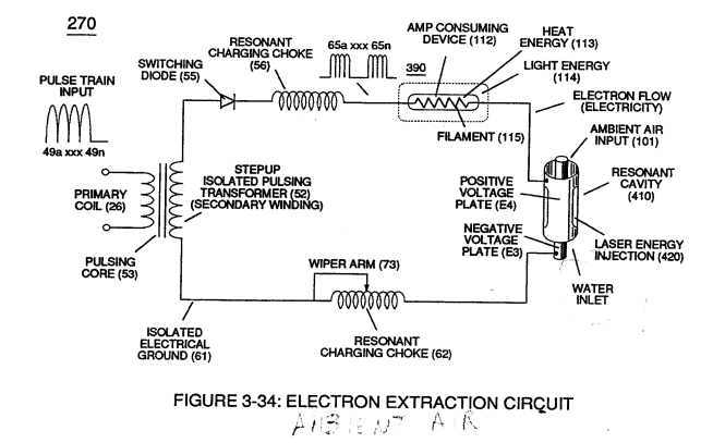
Repetitive formation of electrical voltage force or voltage intensity (65a xxx 65n) of Figure (3-21) attracts and causes liberated electrons (117a,xxx 117n) to move electrically away from gas resonant cavity (410) and physically interact with light bulb filament (115) to initiate and perform kinetic conversion process (390), as further illustrated in (270) of Figure (3-34).
-
voltage intensity (65a xxx 65n)
voltage intensity (65a xxx 65n) of Figure (3-21)
-
voltage potential (65)
The electron conversion process (390) is, of course, terminated when applied pulse voltage potential (65) is switched off.
-
voltage intensity (65a xx 65n)
Pulsating voltage potential or voltage intensity (65a xx 65n) is adjusted, also, to "tune-in" to the resonant properties of ambient air gases (101) since ambient air gases (101) exhibits a dielectric value (air-gap of one inch resisting electron arc-over of up to 17,000 volts applied) between voltage plates (E3) and (E4), forming capacitor (410) of Figure (3-34).
-
pulse frequency (65a xxx 65n)
Applied voltage amplitude (Va xxx Vn), applied voltage pulse frequency (65a xxx 65n), and applied current pulse train (126a xxx 126n) are design variable to "tune-in" to the resonant properties of gas atom (101) while stimulating and performing gas process (260) which attenuates electrical force (AA') of Figure (3-35) to disrupt the mass equilibrium of gas atom (104).