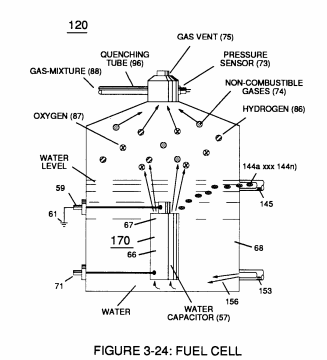
Figure (3-24)
Fuel Cell
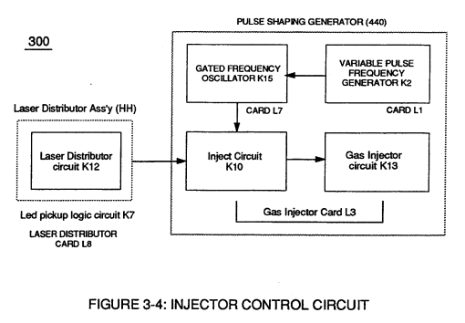
Also written Injector Control Circuit
How it is written
- (3-24) 27×
Drawings 5
-
Figure (3-24) · Voltage Amplitude Control Circuit (50)
-
Figure (3-24) · Electrical Polarization process
-
Fuel Cell (120) of Figure (3-24) · Operational Parameters
-
Captioned as this figure · WFC 422DA - Illustrations
-
Figure (3-24) · Inductance (FL)
On this figure 19
- 34 Gas Mixing Disc
- 35 Resonant Cavity Zone
- 65 Voltage Potential
- 66 Positive Voltage Potential
- 68 Water Bath
- 73 Core-Slug
- 75 Gas Pressure Release Valve
- 85 Water Molecule
- 86 Hydrogen
- 87 Oxygen
- 88 Fuel-Gases
- 98 Gas Ignition Process
- 120 Fuel Cell
- 144 Water Contaminates
- 156 Purified Water Bath
- 165 Kinetic Energy
- 166 Opposite Voltage Pulses
- 167 Opposite Voltage Pulses
- 170 Resonant Cavity
Where it is named · 27
Voltage Amplitude Control Circuit (50) 3×
-
If gas pressure (34a xx) should exceed gas point (35) during injector off-time, gas pressure release valve (75) of Figure (3-24) (gas venting 37 of Figure 3-15) expels Fuel gases (88) until gas point (34) is either reached or a delay timing circuit activates Safety Control Circuit (14) of Figure (3-6) which, in turns, switches …
-
Figure (3-24)
Voltage Intensifier Circuit (60) 5×
-
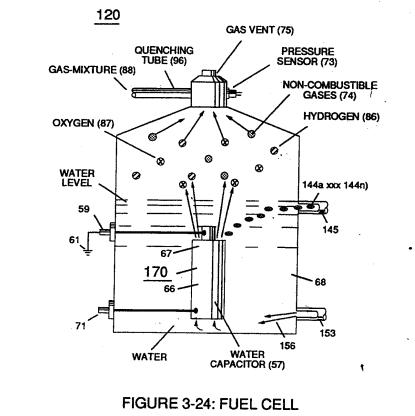
These controlled and variable pulse features are, now, translated to Resonant Charging pulse train (65a xxx 65n) of Figure (3-21) via Unipolar pulse train (64a xxx 64n) of Figure (3-20) during Resonant Action (160) of Figure (3-26) when signal coupling is applied across Resonant Cavity (170) of Figure (3-24) via positive voltage zone (66).
-
Figure (3-24)
-
Figure (3-24)
-
Inherently, then, pulsing core (53) of Figure (3-23) aids amp restriction while voltage intensifier circuit (190) is being "tuned" (adjusting pulse train 49a xxx 49n pulse-frequency 63 via pulse frequency generator 70 of figure 3-5) to match the resonant frequency properties of water bath (68) of Figure (3-22), as illustrated in Fuel Cell (120) of Figure (3-24).
Electrical Polarization process 2×
-
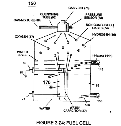
Repetitive duplication of voltage pulse (65a xxx 65n) continues to separate or split apart other water molecules (85a xxx 85n) which, in turns, forms hydrogen (86) and oxygen (87) gas-mixture (88) of Figure (3-24).
-
Figure (3-24)
Resonant Action 3×
-
Figure (3-24)
Gas Modulator Process 6×
-
… Polarization Process (160) of Figure (3-26) is automatically intermixed with released hydrogen (86) and oxygen (87) gas atoms (also derived from water bath 85) to form Fuel-Gas mixture (88) of Figure (3-24) having a hydrogen gas burn-rate of approximately 47 centimeters per seconds (cm/see) in ambient air, as illustrated in (330) of Figure (3-37).
-
Fuel-Gas mixture (88) of Figure (3-24)
-
Figure (3-24)
-
Water bath (68) of Figure (3-39) as to Figure (3-24), now, becomes and functions as a "Gas Mixing Regulator" since the highest possible thermal explosive energy yield (gtnt) obtainable from hydrogen during "normal" gas ignition (98) is the exact composition of water where two hydrogen atoms (86a / 86b) unite with oxygen atom (87).
-
The resultant and on-going Gas Modulator Process (320) of Figure (3-36), now, allows hydrogen fuel cell (120) of Figure (3-24) to be retrofitted to any conventional internal combustion engine (55) of Figure (3-1) without engine change by simply metering the proper amount of exhaust gases (99a xxx 99n) to comply with and co-e …
-
Fuel-Gas mixture (88) of Figure (3-24)
Impurity Extraction Process 2×
-
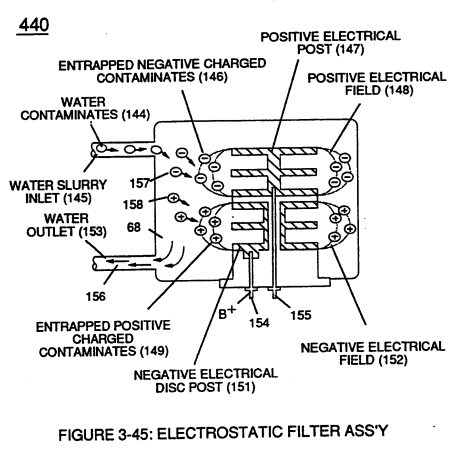
Suspended and dissolved water contaminates (144a xxx 144n) (typically 20 ppm to 40 ppm in natural water) of Figure (3-24) being uniformly released from and superimposed onto remaining water bath (68) during Resonant Action (170) are directed to and passes through water inlet line (145)
Steam Resonator 2×
-
To further ensure proper Fuel Cell optional performance during frigid or below freezing weather conditions, Steam Resonator assembly (450) of Figure (3-46) is inserted into Fuel Cell (120) of Figure (3-24) and thermostatically activated via Voltage Intensifier Circuit (165) which directly applies an alternate or opposite (166/167) electrical voltage pulses (during amp restriction) in a sequential manne …
-
Figure (3-24)
Operational Parameters 2×
-
Fuel Cell (120) of Figure (3-24)
Inductance (FL) 2×
-
Electron interaction (movement of electrons through the liquid medium of water) is further inhibited since natural water contaminates (144a xxx 144n) of Figure (3-24) is normally less than 20 ppm.
-
Figure (3-24)