(120)
Fuel Cell
Also written hydrogen fuel cell · Electron Extraction Circuit · Extraction Circuit · Resonant Cavity Assembly
Where it is first named
This "shut-down" or "Switch-off" condition helps provide a fail-safe operable Fuel Cell (120) of Figure (3-20) by negating acceleration beyond driver's control.
How it is written
- (120) 16×
Drawings 57
-
Carries this number · Laser Accelerator Assembly
-
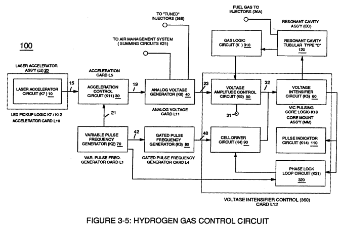
Figure (3-5) · Acceleration Control Circuit (30)
-
Analog Voltage Circuit (40), as shown in Figure (3-5) · Acceleration Control Circuit (30)
-
Figure (3-5) · Acceleration Control Circuit (30)
-
Figure (3-5) · Analog Voltage generator (40)
-
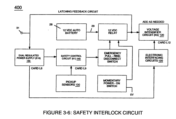
Figure (3-6) · Voltage Amplitude Control Circuit (50)
-
Figure (3-1) · Voltage Amplitude Control Circuit (50)
-
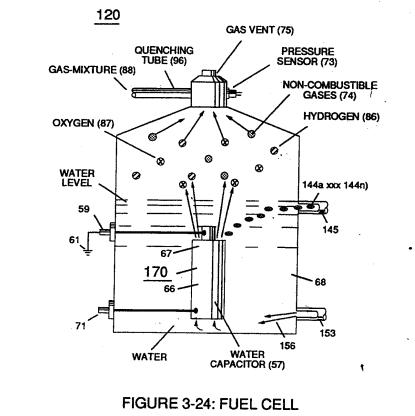
Figure (3-24) · Voltage Amplitude Control Circuit (50)
-
Figure (3-6) · Cell Driver Circuit (90)
-
Figure (3-24) · Electrical Polarization process
-
To further prevent voltage fluctuation during resonant action, Phase Lock Loop technique of Pulse Indicator circuit (110) is utilized during pulsing operations. · Resonant Action
-
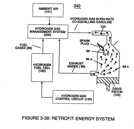
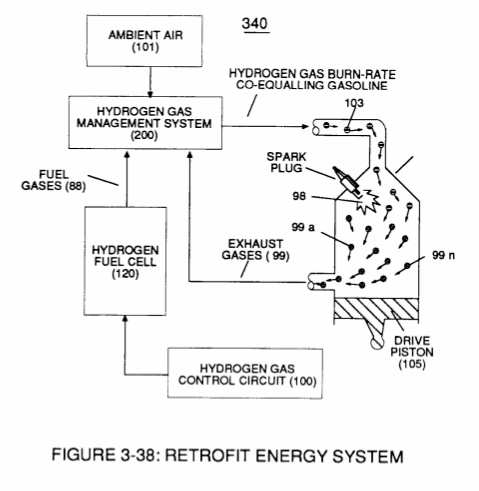
(340) of Figure (3-38) · Gas Modulator Process
-
(340) of Figure (3-38) · Gas Modulator Process
-
engine cylinder (102) of Figure (3-38) · Gas Processor
-
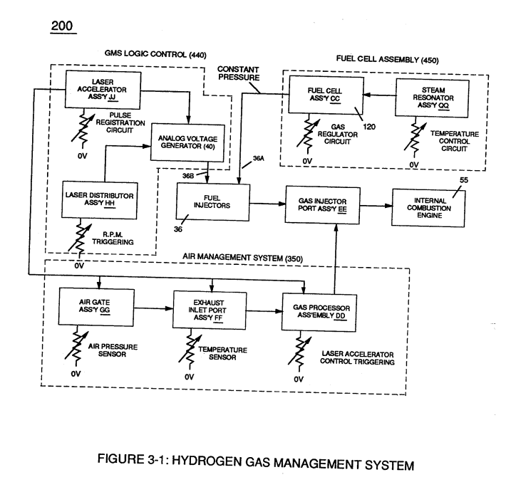
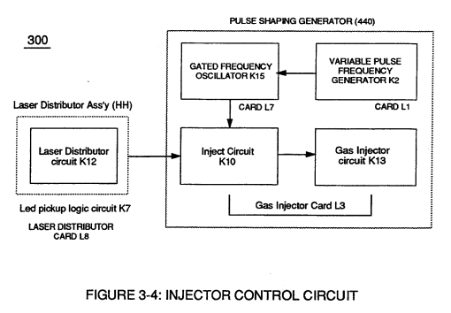
Figure (3-1) · Laser Distributor
-
Figure (3-5) · Laser Distributor
-
Hydrogen Fuel-Gas Assembly (450) of Figure (3-1) · Operational Parameters
-
Fuel Cell (120) of Figure (3-24) · Operational Parameters
-
Carries this number · WFC 422DA - Illustrations
-
Carries this number · WFC 422DA - Illustrations
-
Carries this number · WFC 422DA - Illustrations
-
Carries this number · WFC 422DA - Illustrations
-
Carries this number · WFC 422DA - Illustrations
-
Carries this number · Water Fuel Injection System
-
Carries this number · Electronic Circuit Design
-
Carries this number · Electronic Circuit Design
-
Carries this number · Electronic Circuit Design
-
Carries this number · Electronic Circuit Design
-
Carries this number · Electronic Circuit Design
-
Carries this number · Electronic Circuit Design
-
Carries this number · Electronic Circuit Design
-
Carries this number · Differential Air-Gas Inlet Control
-
Carries this number · Differential Air-Gas Inlet Control
-
Carries this number · Differential Air-Gas Inlet Control
-
Carries this number · Differential Air-Gas Inlet Control
-
Carries this number · Water Fuel Injector (Taper Resonant Cavity Chamber)
-
Carries this number · Water Fuel Injector (Taper Resonant Cavity Chamber)
-
Carries this number · Funneling Effect
-
Carries this number · Steam Resonator Assembly
-
Carries this number · Water Fuel Injection System - Page 1
-
Figure (3-6) · Water Fuel Injection System - Page 1
-
Figure (4-10) · Water Fuel Injection System - Page 2
-
Carries this number · Illustrations
-
Figure (3-24) · Inductance (FL)
-
Figure (3-22) · Analog Voltage generator (40)
-
Figure (3-22) · Voltage Amplitude Control Circuit (50)
-
Figure (3-20) · Voltage Intensifier Circuit (60)
-
Figure (3-22) · Voltage Intensifier Circuit (60)
-
Figure (3-22) · Voltage Dynamics
-
Voltage Intensifier Circuit (60) of Figure (3-22) · Gas Processor
-
The figure it sits on · WFC 422DA - Illustrations
-
The figure it sits on · WFC 422DA - Illustrations
-
Voltage Intensifier Circuit (60) of Figure (3-22) · Instant Explosion of Water
-
(56/62) of Figure (3-22) · Instant Explosion of Water
-
(56) of Figure (3-22) · Instant Explosion of Water
-
Voltage Intensifier Circuit (60) of Figure (3-22) · Propagating Electrical Stress
-
(60) of Figure (3-22) · Propagating Electrical Stress
Where it is named · 16
Laser Accelerator Assembly 1×
-
Fuel Cell (120)
This "shut-down" or "Switch-off" condition helps provide a fail-safe operable Fuel Cell (120) of Figure (3-20) by negating acceleration beyond driver's control.
Analog Voltage generator (40) 1×
-
Resonant Cavity Assembly (120)
Voltage valves or levels (22a xxx 22n) simply controls the applied voltage potential across Resonant Cavity Assembly (120) of Figure (3-22) through voltage amplitude control circuit (50) of Figure (3-5) which is is electrically linked to primary coil (26) of Figure (3-22) of Voltage Intensifier Circuit (60) of Figure (3-5).
Voltage Amplitude Control Circuit (50) 1×
-
Fuel Cell (120)
First, regulates car battery electrical voltage potential (32) of Figure (3-15) being applied to primary coil (26) of Figure (3-21); and secondly, regulates gas pressure of Fuel Cell (120) of Figure (3-22), as graphically depicted in Figure (3-15).
Voltage Intensifier Circuit (60) 1×
-
Fuel Cell (120)
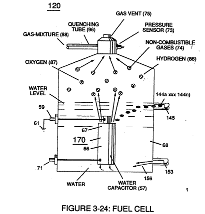
Inherently, then, pulsing core (53) of Figure (3-23) aids amp restriction while voltage intensifier circuit (190) is being "tuned" (adjusting pulse train 49a xxx 49n pulse-frequency 63 via pulse frequency generator 70 of figure 3-5) to match the resonant frequency properties of water bath (68) of Figure (3-22), as illustrated in Fuel Cell (120) of Figure (3-24).
Resonant Action 1×
-
... stabilizing gas production during voltage stimulation (65), as shown in (120) of Figure (3-24).
Gas Modulator Process 1×
-
hydrogen fuel cell (120)
The resultant and on-going Gas Modulator Process (320) of Figure (3-36), now, allows hydrogen fuel cell (120) of Figure (3-24) to be retrofitted to any conventional internal combustion engine (55) of Figure (3-1) without engine change by simply metering the proper amount of exhaust gases (99a xxx 99n) to com …
Impurity Extraction Process 1×
-
Fuel Cell (120)
... producing purified water bath (156) which is recycled back into Fuel Cell (120) of Figure (3-24) since Resonant Action (170) also function as and performs as a water-pump (Gas rising).
Steam Resonator 1×
-
Fuel Cell (120)
To further ensure proper Fuel Cell optional performance during frigid or below freezing weather conditions, Steam Resonator assembly (450) of Figure (3-46) is inserted into Fuel Cell (120) of Figure (3-24) and thermostatically activated via Voltage Intensifier Circuit (165) which directly applies an alternate or opposite (166/167) electrical voltage pulses (during amp restriction) in a …
Operational Parameters 2×
-
Fuel Cell (120)
... especially since Fuel Cell (120) of Figure (3-24) is miniaturized to Water Fuel Injector Plug (40) of Figure (4-2), as further illustrated in WFC memo 423 DA.
Water Fuel Injection System 3×
-
Electron Extraction Circuit (120)
To elevate Energy-flame-temperature still further, help increase fluid-displacement (46/47) while maintaining or reducing the volume flow rate of non-combustible gases (45) during an increase of applied voltage amplitude (Vo x Vn) of Figure (32) as to Voltage Intensifier Circuit (110) of Figure (7) and Electron Extraction Circuit (120) of Figure (8).
-
Extraction Circuit (120)
Voltage Igniter Stage (180) of Figure (3B) as to Voltage Intensifier Circuit (110) Figure (7) as to Extraction Circuit (120) of Figure (8) performs several functions simultaneously to initiate and trigger thermal explosive energy-yield (gtnt) (16) beyond normal gas burning levels:
-
electron extraction circuit (120)
Incoming ambient air gases (5a xxx 5n) become laser primed and ionized when passing through Ambient Air Ionizer (Gas Processor) (80) of Figure (4) as to (10) of Figure (1) since electron extraction circuit (120) of Figure (8) not only captures and consumes ejected electrons (7a cx 7n) of Figure (6); but, also prevents electron flow into destabilizing gas process (180), as so illustrated in Figure (3B).
Water Fuel Injection System - Page 2 1×
-
Electron Extraction Circuit (120)
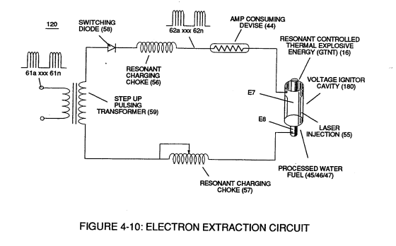
To elevate Energy-flame-temperature still further, simply increase fluid-displacement (46/47) while maintaining or reducing the volume flow rate of non-combustible gases (45) during an increase of applied voltage amplitude (V0 xxx Vo) of Figure (4-2) as to Voltage Intensifier Circuit (110) of Figure (4-9) and Electron Extraction Circuit (120) of Figure (4-10).
Water Fuel Injection System - Page 3 2×
-
electron extraction circuit (120)
Incoming ambient air gases (5a xxx 5n) become laser primed and ionized when passing through Ambient Air Ionizer (Gas Processor) (80) of Figure (4-6) as to (10) of Figure (4-1) since electron extraction circuit (120) of Figure (4-10) not only captures and consumes ejected electrons (7a xx 7n) of Figure (4-8);
-
electron extraction circuit (120) of Figure (4-10)