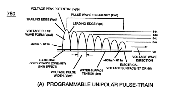
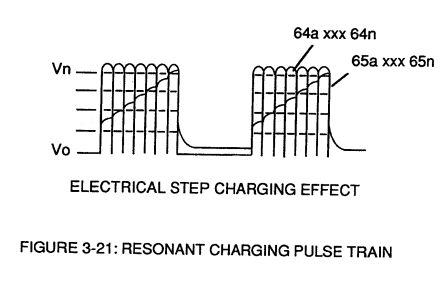
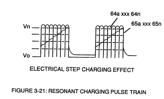
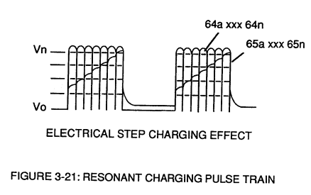
Figure (3-21)
Resonant Charging Pulse Train
How it is written
- (3-21) 16×
Drawings 5
-
Figure (3-21) · Voltage Amplitude Control Circuit (50)
-
Figure (3-21) · Voltage Intensifier Circuit (60)
-
Captioned as this figure · Voltage Dynamics
-
Captioned as this figure · Gas Processor
-
Captioned as this figure · WFC 422DA - Illustrations
On this figure 20
- 1 Negative Charged Hydrogen Electron
- 12 Logic-Point
- 26 Primary Coil
- 32 Analog Signal
- 53 Pulsing Core
- 57 Capacitor
- 60 Voltage Intensifier Circuit
- 61 Negative electrical voltage potential
- 64 Pulse Train
- 65 Voltage Potential
- 66 Positive Voltage Potential
- 67 Opposite Polarity
- 117 Liberated Electrons
- 320 Gas Modulator Process
- Dss Dynamic State Space
- Dvs Dynamic Voltage Stimulation
- Esi Electrical Stress Intensity
- Sss Static State Space
- Vpp Voltage Peak Potential
- Vwp Unipolar Voltage Pulse
Where it is named · 16
Voltage Amplitude Control Circuit (50) 3×
-
Figure (3-21)
-
Variable voltage range (32a xxx 32n) from one (1) up to twelve (12) volts (regulating battery voltage) is applied across primary coil (26) of Voltage Intensifier Circuit (60) of Figure (3-21).
Voltage Intensifier Circuit (60) 9×
-
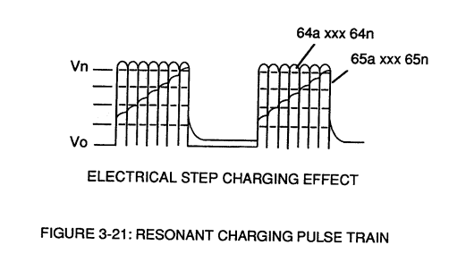
These controlled and variable pulse features are, now, translated to Resonant Charging pulse train (65a xxx 65n) of Figure (3-21) via Unipolar pulse train (64a xxx 64n) of Figure (3-20) during Resonant Action (160) of Figure (3-26) when signal coupling is applied across Resonant Cavity (170) of Figure (3-24) via positive voltage zone (66).
-
Figure (3-21)
-
The resultant signal coupling ( 65a xx 65n ) of Figure (3-21) is accomplished since primary coil (26), pulsing core (53), secondary coil (52), switching diode (55), resonant charging choke (56), resonant cavity assembly (170), natural water (68), and variable resonant charging choke (62) forms Voltage Intensifier Circuit (60) of Figure (3-22), as illustrated in Figure (3-22) as to Figure (3-23).
-
The established resonant frequency is, of course, independent of voltage amplitude, as illustrated in Figure (3-21) as to Figure (3-18).
-
Figure (3-21)
-
During resonant interaction, the incoming unipolar pulse train (64a xxx 64n) of Figure (320) as to Figure (3-21) produces a step charging voltage effect across excitor-array (66/67) (57) as so illustrated in Figure (3-21).
-
During resonant interaction, the incoming unipolar pulse train (64a xxx 64n) of Figure (320) as to Figure (3-21) produces a step charging voltage effect across excitor-array (66/67) (57) as so illustrated in Figure (3-21).
-
Figure (3-21)
Voltage Dynamics 1×
-
Voltage is "electrical pressure" or "electrical force" within electrical circuit (60) and is known as voltage potential (65a xxx 65n) of Figure (3-21).
Gas Processor 2×
-
Repetitive formation of electrical voltage force or voltage intensity (65a xxx 65n) of Figure (3-21) attracts and causes liberated electrons (117a,xxx 117n) to move electrically away from gas resonant cavity (410) and physically interact with light bulb filament (115) to initiate and perform kinetic conversion process (390), as further illustrated in (270) of Figure (3-34).
-
voltage intensity (65a xxx 65n) of Figure (3-21)
8-5 - Energy Vectoring (Ev) 1×
-
… Stimulation (Dvs) since Voltage Peak Potential (Vpp) increases as Voltage Sync-Wave Front (a to b to c and so on) advances in the number of Unipolar Voltage Pulse (s) (Vwp), as illustrated in Figure (3-21) ... causing Dynamic State Space (Dss) or Static State Space (Sss) to be progressively increased in Electrical Stress Intensity (Esi) during a given space-time continuum