(61) · also written as a run, 61a xxx 61n
Negative electrical voltage potential
Also written Isolated electrical ground · Negative electrical ground · Booster Pickup Coils · coil-structure
Where it is first named
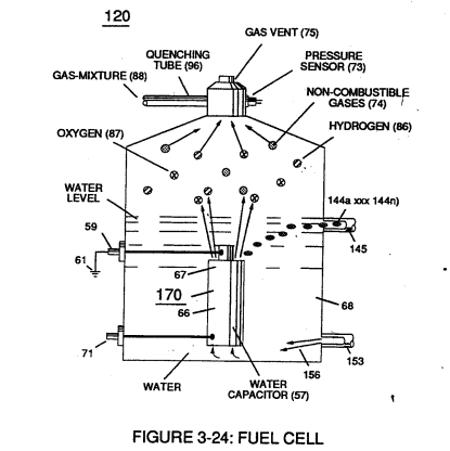
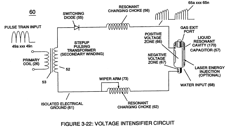
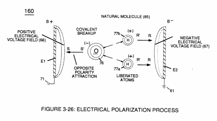
Negative electrical voltage potential (61) of pulse wave (65a xxx 65n) of Figure (3-21) is simultaneously applied to negative voltage zone (67) via Resonant Charging Choke (62) of Figure (3-22) which is electrically linked to opposite end of Primary Coil (26).
How it is written
- (61) 6×
- (61a xxx 61n) 2×
- (61a-61b-61c-61n) 1×
61a xxx 61n is Meyer's shorthand for a run of the same thing: 61a is the first, 61n the last, and the x's stand for however many lie between. Every stage of the run is this one numeral.
Drawings 50
-
Figure (3-22) · Analog Voltage generator (40)
-
Figure (3-22) · Voltage Amplitude Control Circuit (50)
-
Figure (3-24) · Voltage Amplitude Control Circuit (50)
-
Figure (3-26) · Voltage Intensifier Circuit (60)
-
Figure (3-23) · Voltage Intensifier Circuit (60)
-
Figure (3-22) · Voltage Intensifier Circuit (60)
-
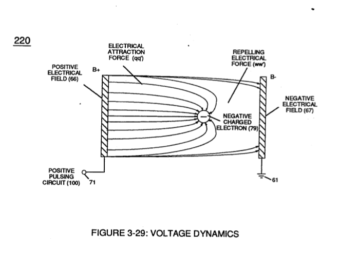
Figure (3-22) · Voltage Dynamics
-
In both cases, electrical charge deflection or movement is directly related to applied voltage (65). · Voltage Dynamics
-
Figure (3-24) · Electrical Polarization process
-
Voltage Intensifier Circuit (60) of Figure (3-22) · Gas Processor
-
(270) of Figure (3-34) · Gas Processor
-
Carries this number · WFC 422DA - Illustrations
-
Carries this number · WFC 422DA - Illustrations
-
Carries this number · WFC 422DA - Illustrations
-
Carries this number · WFC 422DA - Illustrations
-
Carries this number · WFC 422DA - Illustrations
-
Carries this number · WFC 422DA - Illustrations
-
Carries this number · WFC 422DA - Illustrations
-
Carries this number · WFC 422DA - Illustrations
-
Electron Ejection Process (230) of Figure (29) · Water Fuel Injector (Taper Resonant Cavity Chamber)
-
Figure (25) · Water Fuel Injector (Taper Resonant Cavity Chamber)
-
Carries this number · Funneling Effect
-
Carries this number · Funneling Effect
-
Figure (4-10) · Water Fuel Injection System - Page 2
-
Carries this number · Energy Pumping Action
-
(85) of Figure (3-26) · In Application of Usage
-
(160) of Figure (3-26) · In Application of Usage
-
(270) of (3-34) · In Application of Usage
-
Voltage Intensifier Circuit (60) of Figure (3-22) · Instant Explosion of Water
-
(56/62) of Figure (3-22) · Instant Explosion of Water
-
(57 of Figure 3- 25 ~35 of Figure 6-2) · Instant Explosion of Water
-
(56) of Figure (3-22) · Instant Explosion of Water
-
(85) of Figure (3-26) · Resistance (Rs)
-
Voltage Dynamics (220) of Figure (3-29) · Electron Bounce Phenomenon
-
(170) of Figure (3-25) · 8-4 - State Space (Sp)
-
Figure (820A) of Figure (8-6) · 8-7 - Application of Usage
-
Voltage Dynamics (220) of Figure (3-29) · WFC Exhaust Air Reclaimer
-
Figure (3-34) · Propagating Electrical Stress
-
Voltage Intensifier Circuit (60) of Figure (3-22) · Propagating Electrical Stress
-
(160) of Figure (3-26) · Propagating Electrical Stress
-
(60) of Figure (3-22) · Propagating Electrical Stress
-
blocking diode (55) of Figure (3-34) · Voltage to Amp Differential Ratio
-
Figure (3-21) · Voltage Amplitude Control Circuit (50)
-
Figure (3-21) · Voltage Intensifier Circuit (60)
-
The figure it sits on · Voltage Dynamics
-
Figure (3-26) · Electrically Charged Water Molecule
-
The figure it sits on · Gas Processor
-
The figure it sits on · WFC 422DA - Illustrations
-
(160) of Figure (3-26) · Water Fuel Injection System - Page 1
-
The figure it sits on · WFC Exhaust Air Reclaimer
Where it is named · 9
Voltage Intensifier Circuit (60) 4×
-
Negative electrical voltage potential (61)
Negative electrical voltage potential (61) of pulse wave (65a xxx 65n) of Figure (3-21) is simultaneously applied to negative voltage zone (67) via Resonant Charging Choke (62) of Figure (3-22) which is electrically linked to opposite end of Primary Coil (26).
-
Negative electrical ground (61)
Negative electrical ground (61) of voltage Intensifier circuit (60) of Figure (3-22) is electrically isolated from primary electrical ground (48) of Figure (3-22).
-
Isolated electrical ground (61)
Isolated electrical ground (61) prevents electron flow from input circuit ground (48).
-
Once voltage-pulse (64) is terminated or switch-off, voltage potential returns to "ground-state" (61) or near ground-state (diode 55 maintains voltage charged across capacitor 57) to start the voltage deflection process over again as pulse train (64a xxx 64n) continues to be duplicated.
Water Fuel Injector (Taper Resonant Cavity Chamber) 1×
-
Booster Pickup Coils (61a xxx 61n)
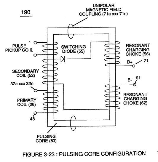
Sequential Switch Circuit (59) simply switches in and out Booster Pickup Coils (61a xxx 61n) in series electrical hookup with Secondary Coil (53) output to elevate voltage intensity across Resonant Charging Chokes (56/57).
Funneling Effect 3×
-
… ce again, inductance core-slug (73) (magnetic core material) advances (via solenoid Control 74) toward, passes through inside coil-wrap (250) in linear manner to "Switch-Off" each adjacent coil-stage (61a xxx 61n) by "Shunting" or "Redirecting" induced voltage intensity (Vmn xxx Vma) to its respective electrical out-put leads (72n - 72c - 72b - 72a), as shown in Figure (20).
-
coil-structure (61)
This "Shunting Effect" occurs when the magnetic field strength of each individual coil-structure (61) (being electrically energized) induces and forms magnetic core-field (75) which opposes and stops current flow within the exposed coil-stage (61a-61b-61c-61n).
-
This "Shunting Effect" occurs when the magnetic field strength of each individual coil-structure (61) (being electrically energized) induces and forms magnetic core-field (75) which opposes and stops current flow within the exposed coil-stage (61a-61b-61c-61n).
WFC Exhaust Air Reclaimer 1×
-
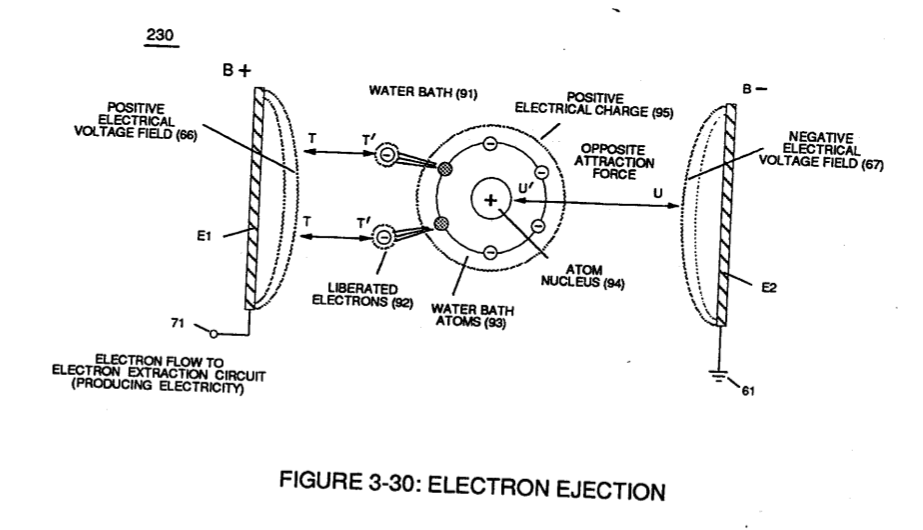
.•• performing the same function as Electrical Polarization Process (160) of Figure (3-26) by which the positive electrical voltage potential (71) attracts the negative charged oxygen atom; while, simultaneously, negative electrical voltage potential (61) attracts the positive charged Nitrogen Atom