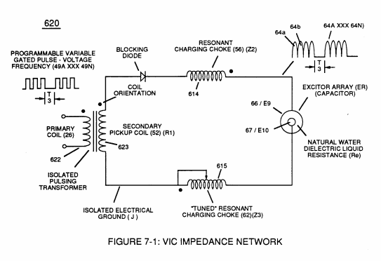
(R1)
(R1)
Where it is first named
Since pickup coil (A) is also composed of or made of resistive wire-coil (R1) , then, total circuit resistance is given by
How it is written
- (R1) 1×
- (R1 + Z2 + Z3 + Re) 1× with (Z2) Resonant Choke Coils Electromagnetic Fields Intensity, (Z3) Resonant Choke Coils Electromagnetic Fields Intensity, (Re) Water
Drawings 13
-
Stanley A. Meyer Page_6 of 28 · WFC 417 — WFC 417
-
The primary coil is electrically isolated (no electrical connection between primary and secondary coil) to form Voltage Intensifier Circuit (AA) Figure (1-1). · Pulsing Transformer
-
(620) of Figure (7-1) · Instant Explosion of Water
-
(620) of Figure (7-1) · Resistance (Rs)
-
(614) of Figure (7-1) · Inductance (FL)
-
Inductor (614) of Figure (7-1) · Inductance (FL)
-
(614) of (7-1) · Inductance (FL)
-
Figure (7-1) · Capacitance (Cd)
-
(E1/E2) of Figure (1-1) page (1-13) · Taper Resonant Capacitor (ERt)
-
Carries this number · WFC 427 Illustrations
-
Carries this number · WFC 427 Illustrations
-
Figure (1-1) · Propagating Electrical Stress
-
(620) of figure (7-1) · Voltage to Amp Differential Ratio
Where it is named · 2
WFC 417 — WFC 417 1×
-
Since pickup coil (A) is also composed of or made of resistive wire-coil (R1) , then, total circuit resistance is given by
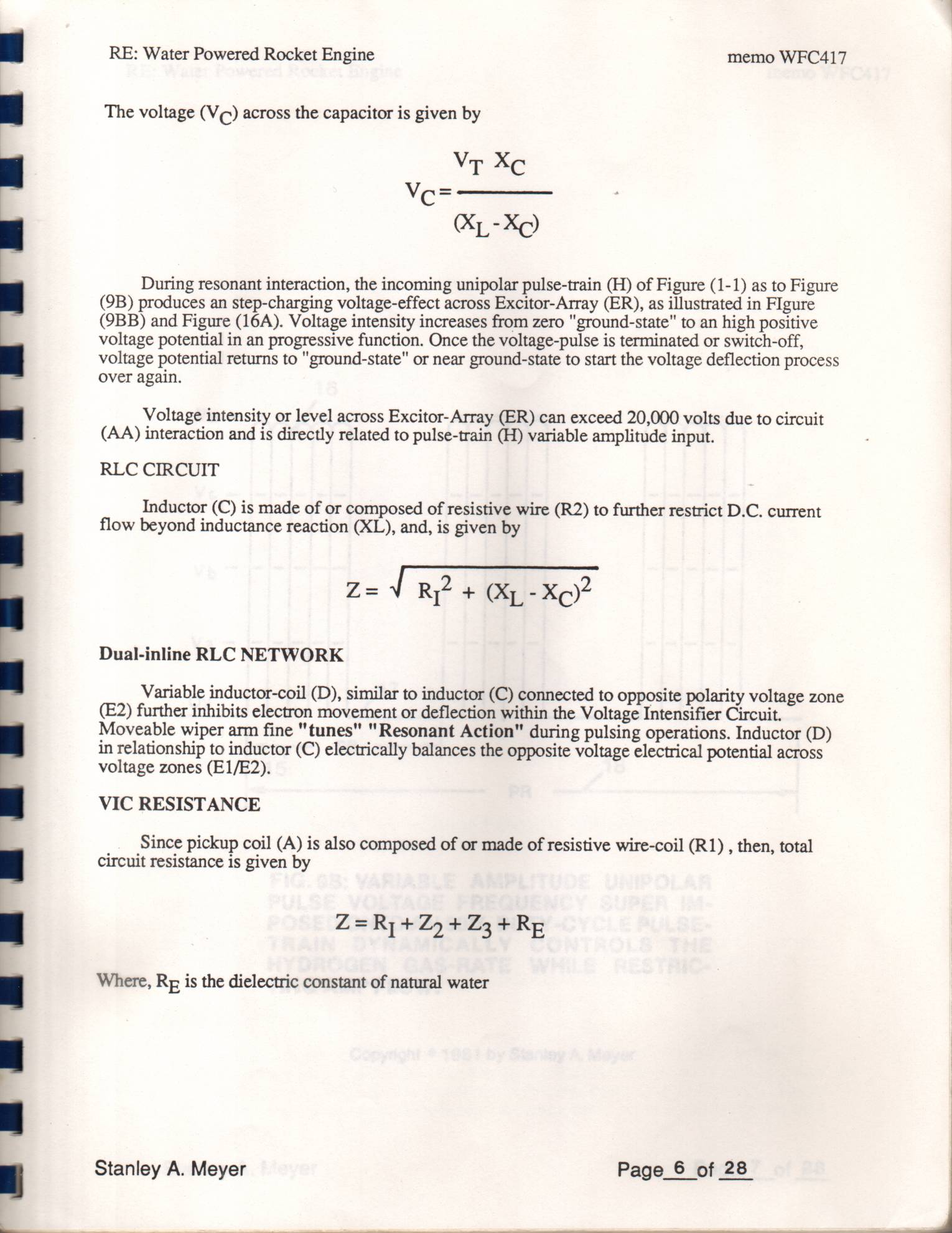
Instant Explosion of Water 1×
-
Switching Diode (55) of Figure (3-22) prevents Bidirectional electron flow (current flow in one direction only) since Blocking Diode (55) only conducts "current flow" in the direction of schematic-arrow while being placed in-line with VIC Circuit impedance interaction (R1 + Z2 + Z3 + Re), as mathematically extrapolated in Circuit Equation (Eq 9)