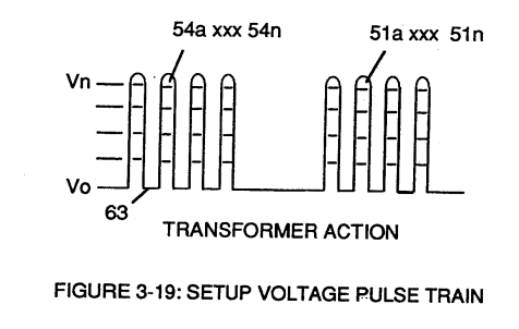
Figure (3-19)
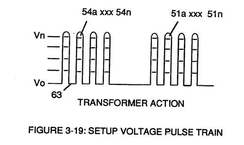
Setup Voltage Pulse Train
Also written Setup Voltage Pulse Train (64
How it is written
- (3-19) 7×
Drawings 4
-
Figure (3-19) · Cell Driver Circuit (90)
-
Figure (3-19) · Voltage Intensifier Circuit (60)
-
Captioned as this figure · WFC 422DA - Illustrations
-
Captioned as this figure · 8-1 - Propagating "Resonant Action" By Voltage Tickling of State Space
On this figure 9
- 26 Primary Coil
- 48 Water-fuel mixture
- 51 Opposite Electrical Voltage Fields
- 56 Resonant Charging Choke
- 57 Capacitor
- 63 Resonant frequency
- V Voltage Amplitude
- V0 Voltage Amplitude
- Vo Applied Voltage Amplitude
Where it is named · 7
Cell Driver Circuit (90) 2×
-
In either case, the resultant or varied pulse train (47a xxx 47n) (calibration of 44a xxx 44n) becomes incoming gated pulse signal (48) of figure (3-5) to cell driver circuit (90) of Figure (3-5) which performs a switching function by switching "off' and "on" electric ground being applied to opposite side (48) of primary coil (26) of Figure (3-19).
-
Figure (3-19)
Voltage Intensifier Circuit (60) 5×
-
Figure (3-19)
-
Analog voltage signal (32a xxx 32n) of Figure (3-15) allows pulse train (51a xxx 51n) voltage amplitude (V0 xxx Vn) of Figure (3-19) to vary from one up to twelve volts (battery supply 28 of Figure 3-6 by attenuating Laser Accelerator circuit (10) of Figure (3-5) via Hydrogen Gas Control Circuit (100).
-
Pulsing transformer (26/52) of Figure (3-22) steps up voltage amplitude or voltage potential (Vo xxx Vn) of Figure (3-19) during pulsing operations.