(55) · also written as a run, 55a xxx 55n
Switching Diode
Also written diode · Blocking Diode · internal combustion engine
Where it is first named
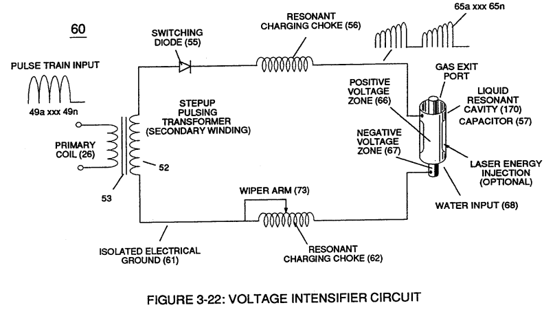
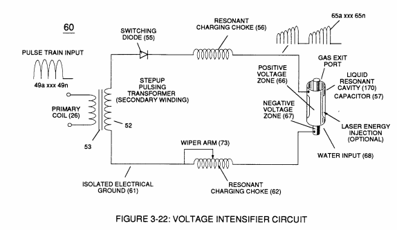
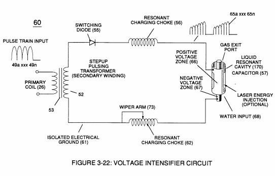
The resultant signal coupling ( 65a xx 65n ) of Figure (3-21) is accomplished since primary coil (26), pulsing core (53), secondary coil (52), switching diode (55), resonant charging choke (56), resonant cavity assembly (170), natural water (68), and variable resonant charging choke (62) forms Voltage Intensifier Circuit (60) of Figure (3-22), as illustrated in Figure (3-22) as to Figure (3-23).
How it is written
- (55) 13×
- (55'-RR'a xxx SS'-RR'n) 1×
55a xxx 55n is Meyer's shorthand for a run of the same thing: 55a is the first, 55n the last, and the x's stand for however many lie between. Every stage of the run is this one numeral.
Drawings 65
-
Figure (3-22) · Analog Voltage generator (40)
-
Figure (3-22) · Voltage Amplitude Control Circuit (50)
-
Figure (3-23) · Voltage Intensifier Circuit (60)
-
Figure (3-22) · Voltage Intensifier Circuit (60)
-
Figure (3-22) · Voltage Dynamics
-
Figure (3-23) · Voltage Dynamics
-
Voltage Intensifier Circuit (60) of Figure (3-22) · Gas Processor
-
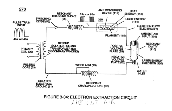
(270) of Figure (3-34) · Gas Processor
-
Carries this number · WFC 422DA - Illustrations
-
Carries this number · WFC 422DA - Illustrations
-
Carries this number · WFC 422DA - Illustrations
-
Carries this number · WFC 422DA - Illustrations
-
Carries this number · Water Fuel Injection System
-
3-4 Inner Core Bobbin · Voltage Intensifier Coil Assembly
-
Carries this number · Electronic Circuit Design
-
Carries this number · Funneling Effect
-
2-3 Water Inlet Housing · Water Fuel Injector Illustrations
-
Figure (4-10) · Water Fuel Injection System - Page 2
-
(270) of (3-34) · In Application of Usage
-
(190) of Figure (3-23) · Tri - Coil Construction
-
Voltage Intensifier Circuit (60) of Figure (3-22) · Instant Explosion of Water
-
(56/62) of Figure (3-22) · Instant Explosion of Water
-
(56) of Figure (3-22) · Instant Explosion of Water
-
Inductance Pulsing-Core (190) of Figure (3-23) · Inductance Reactance (Rs - Cd - FL)
-
Carries this number · Electron Bounce Phenomenon
-
Figure (3-34) · Propagating Electrical Stress
-
Voltage Intensifier Circuit (60) of Figure (3-22) · Propagating Electrical Stress
-
(60) of Figure (3-22) · Propagating Electrical Stress
-
blocking diode (55) of Figure (3-34) · Voltage to Amp Differential Ratio
-
The figure it sits on · Laser Accelerator Assembly
-
Figure (3-1) · Voltage Amplitude Control Circuit (50)
-
Figure (3-20) · Voltage Intensifier Circuit (60)
-
To further prevent voltage fluctuation during resonant action, Phase Lock Loop technique of Pulse Indicator circuit (110) is utilized during pulsing operations. · Resonant Action
-
(340) of Figure (3-38) · Gas Modulator Process
-
(340) of Figure (3-38) · Gas Modulator Process
-
engine cylinder (102) of Figure (3-38) · Gas Processor
-
Figure (3-1) · Laser Distributor
-
Hydrogen Fuel-Gas Assembly (450) of Figure (3-1) · Operational Parameters
-
The figure it sits on · WFC 422DA - Illustrations
-
The figure it sits on · WFC 422DA - Illustrations
-
The figure it sits on · Water Fuel Injection System
-
The figure it sits on · Water Fuel Injection System - Page 1
-
The figure it sits on · VIC Matrix Circuit
-
(700) of Figure (7-9) · Instant Explosion of Water
-
(T2) of Figure (7-8) · Instant Explosion of Water
-
Figure (7-8) · Resistance (Rs)
-
(690) of Figure (7-8) · Resistance (Rs)
-
(690) of Figure (7-8) · Inductance (FL)
-
(690) of Figure (7-8) · Capacitance (Cd)
-
(690) of Figure (7-8) · Inductance Reactance (Rs - Cd - FL)
-
"Electron Bounce" phenomenon (700) of Figure (7-9) · Inductance Reactance (Rs - Cd - FL)
-
Figure (7-8) · Inductance Reactance (Rs - Cd - FL)
-
(690) of Figure (7-8) · Taper Resonant Capacitor (ERt)
-
690 of Figure 7-8 · Circuit Resistance
-
"Electron Clustering" (Grouping/collecting negative charged particles at a given point) (700) of Figure (7-9) · Transformer Action
-
(52) of Figure (7-8) · Electron Bounce Phenomenon
-
(700) of Figure (7-9) · Electron Bounce Phenomenon
-
(690) of Figure (7-8) · 8-2 - Traveling Voltage Wave-Guides
-
(631) of Figure (7-9) · 8-3 - Electrical Voltage-Pulse Wave-Transmission
-
(52) of Figure (7-8) · 8-3 - Electrical Voltage-Pulse Wave-Transmission
-
(Cp) of Figure (7-8) · 8-4 - State Space (Sp)
-
(690) of Figure (7-8) · 8-6 - VIC Voltage Sync-Pulse Circuit
-
(Cp) of (7-8) · 8-6 - VIC Voltage Sync-Pulse Circuit
-
(690) of Figure (7-8) · Propagating Electrical Stress
-
The figure it sits on · WFC 429 - Illustrations
Where it is named · 14
Voltage Intensifier Circuit (60) 3×
-
switching diode (55)
The resultant signal coupling ( 65a xx 65n ) of Figure (3-21) is accomplished since primary coil (26), pulsing core (53), secondary coil (52), switching diode (55), resonant charging choke (56), resonant cavity assembly (170), natural water (68), and variable resonant charging choke (62) forms Voltage Intensifier Circuit (60) of Figure (3-22), as illustrated in Figure (3-22) as to Figure (3-23).
-
Switching diode (55)
Switching diode (55) of Figure (3-22) not only acts as a blocking diode by preventing electrical "shorting" to secondary coil (52) during pulse off-time (69) of Figure (3-20) since diode (55) "only" conducts electrical energy in the direction of schematic arrow;
-
diode (55)
Switching diode (55) of Figure (3-22) not only acts as a blocking diode by preventing electrical "shorting" to secondary coil (52) during pulse off-time (69) of Figure (3-20) since diode (55) "only" conducts electrical energy in the direction of schematic arrow;
Gas Modulator Process 3×
-
internal combustion engine (55)
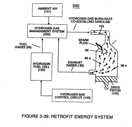
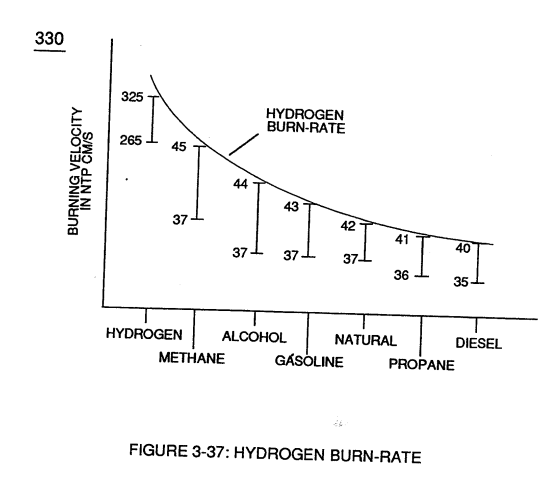
To further reduce hydrogen burn-rate (330) of Figure (3-37) to other fossil-fuel burning levels, additional non-combustible gases (99a xxx 99n) (supplied via ambient air 101) is added to gas-mixture (88) by way of gas ignition process (98) occurring inside internal combustion engine (55) piston cylinder (102), as illustrated in (340) of Figure (3-38).
-
internal combustion engine (55)
The resultant and on-going Gas Modulator Process (320) of Figure (3-36), now, allows hydrogen fuel cell (120) of Figure (3-24) to be retrofitted to any conventional internal combustion engine (55) of Figure (3-1) without engine change by simply metering the proper amount of exhaust gases (99a xxx 99n) to comply with and co-equaling any type or different fossil-fuel burning levels, as further i …
-
internal combustion engine (55)
In terms of operability and performance, gas modulator process (320) continues to allow a conventional internal combustion engine (55) to run on ambient air gases; while, fuel-gas (88) not only cuts back and reduces oxygen extraction form ambient air (101) but produces a environmentally safe exhaust gases since non-combustible gases …
Instant Explosion of Water 5×
-
Switching Diode (55)
VIC voltage circuit (60) utilizes copper wire-wrap to form Resonant Charging Chokes (56/62) of Figure (3-22) in conjunction with Switching Diode (55) to encourage and make use of "Electron Bounce" phenomena (700) of Figure (7-9) to help promote Step Charging Effect (628) of Figure (7-7) by preventing electrical discharge of Resonant Cavity (140 - …
-
Switching Diode (55)
Switching Diode (55) of Figure (3-22) prevents Bidirectional electron flow (current flow in one direction only) since Blocking Diode (55) only conducts "current flow" in the direction of schematic-arrow while being placed in-line with VIC Circuit impedance interaction (R1 + Z2 + Z3 + Re), as mathematically extrapolated in Circuit Equation (Eq 9)
-
Blocking Diode (55)
Switching Diode (55) of Figure (3-22) prevents Bidirectional electron flow (current flow in one direction only) since Blocking Diode (55) only conducts "current flow" in the direction of schematic-arrow while being placed in-line with VIC Circuit impedance interaction (R1 + Z2 + Z3 + Re), as mathematically extrapolated in Circuit Equation (Eq 9)
-
(55) of Figure (3-22)
-
Diode (55)
... Diode (55) being placed between Secondary Pickup Coil (52) and Resonant Charging Choke (56) to act as an electronic switch in open-position during pulse off-time (T2) of Figure (7-8) while preventing electron flow in reverse direction when Inductor (L1) collapsing electromagnetic field (FL1) produces another unipolar pulse wave-form (64a - 64b).
Mode of Operability 1×
-
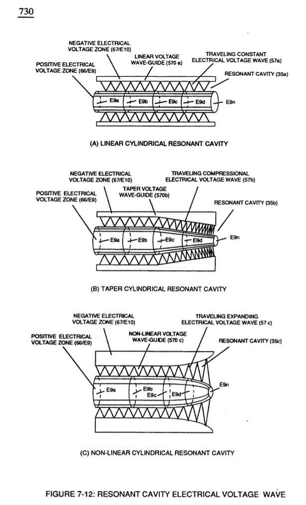
Voltage Compressional Wave-form (35b) and Expanding Voltage Waveform (35c) increases the intensity of applied pulsating opposite electrical attraction force (55'-RR'a xxx SS'-RR'n) even further during each new pulse-cycle (T2 next T2) across water gap (616)
Voltage to Amp Differential Ratio 2×
-
... allowing each/both bifilar coil assembly (56/62a xxx 56/62n -S- SS56/62a xxx SS56/62n) to be electrically and magnetically energized in the same progressive direction toward Water Gap (Cp) and away from blocking diode (55) of Figure (3-34) as to Figure (10-1) and Figure (10-3)
-
blocking diode (55) of Figure (3-34)