(53)
Pulsing Core
Also written Unipolar Pulsing Core · magnetic pulsing core · Secondary Coil · Voltage Transformer · Inductance Core
Where it is first named
variable amplitude pulse-train (51a xxx 51n) of Figure (3-19) is electromagnetically coupled (transformer action) to secondary coil (52) of Figure (3-22) by way of pulsing core (53) of Figure (3-23) as to Figure (3-22).
How it is written
- (53) 16×
- (26 - 53 - 52) 2× with (26) Primary Coil, (52) Secondary Coil
- (52/53) 1× with (52) Secondary Coil
Drawings 64
-
Stanley A. Meyer Page_4 of 28 | · WFC 417 — WFC 417
-
The primary coil is electrically isolated (no electrical connection between primary and secondary coil) to form Voltage Intensifier Circuit (AA) Figure (1-1). · Pulsing Transformer
-
Figure (1-4) · LC Circuit
-
Figure (3-23) · Voltage Intensifier Circuit (60)
-
Figure (3-23) · Voltage Dynamics
-
(270) of Figure (3-34) · Gas Processor
-
Carries this number · WFC 422DA - Illustrations
-
Carries this number · WFC 422DA - Illustrations
-
Carries this number · Water Fuel Injection System
-
Carries this number · Electronic Circuit Design
-
Electronic Circuit (110) of Figure (7) · Water Fuel Injector (Taper Resonant Cavity Chamber)
-
thereby, attenuating voltage amplitude (voltage intensity) beyond Secondary Coil (53) voltage levels (71), as illustrated in (220) of Figure (18). · Funneling Effect
-
Figure (4-9) · Water Fuel Injection System - Page 2
-
(110) of Figure (4-9) · In Application of Usage
-
(270) of (3-34) · In Application of Usage
-
coil-structures (580) of Figure (6-1) · Voltage Intensifier Coil-Assembly
-
(190) of Figure (3-23) · Tri - Coil Construction
-
Carries this number · VIC Matrix Circuit
-
Figure (1-1) (Memo WFC 420) · Instant Explosion of Water
-
(700) of Figure (7-9) · Instant Explosion of Water
-
(T2) of Figure (7-8) · Instant Explosion of Water
-
Figure (7-8) · Resistance (Rs)
-
(110) of Figure (4-9) · Resistance (Rs)
-
(690) of Figure (7-8) · Resistance (Rs)
-
Figure (7-13) · Inductance (FL)
-
(580) of Figure (6-1) · Inductance (FL)
-
(690) of Figure (7-8) · Inductance (FL)
-
(690) of Figure (7-8) · Capacitance (Cd)
-
(690) of Figure (7-8) · Inductance Reactance (Rs - Cd - FL)
-
"Electron Bounce" phenomenon (700) of Figure (7-9) · Inductance Reactance (Rs - Cd - FL)
-
Inductance Pulsing-Core (190) of Figure (3-23) · Inductance Reactance (Rs - Cd - FL)
-
Figure (7-8) · Inductance Reactance (Rs - Cd - FL)
-
(580) of Figure (6-1) · Multi-layer Coil
-
(E1/E2) of Figure (1-1) page (1-13) · Taper Resonant Capacitor (ERt)
-
(690) of Figure (7-8) · Taper Resonant Capacitor (ERt)
-
690 of Figure 7-8 · Circuit Resistance
-
"Electron Clustering" (Grouping/collecting negative charged particles at a given point) (700) of Figure (7-9) · Transformer Action
-
Carries this number · Electron Bounce Phenomenon
-
(52) of Figure (7-8) · Electron Bounce Phenomenon
-
(700) of Figure (7-9) · Electron Bounce Phenomenon
-
(see 740 of Figure 7-13) · Voltage Amplitude Switch-Off
-
Carries this number · WFC 426 - Illustrations
-
Carries this number · WFC 426 - Illustrations
-
(580) of Figure (6-1) (WFC memo 425) · 8-2 - Traveling Voltage Wave-Guides
-
(690) of Figure (7-8) · 8-2 - Traveling Voltage Wave-Guides
-
(631) of Figure (7-9) · 8-3 - Electrical Voltage-Pulse Wave-Transmission
-
(52) of Figure (7-8) · 8-3 - Electrical Voltage-Pulse Wave-Transmission
-
(Cp) of Figure (7-8) · 8-4 - State Space (Sp)
-
(690) of Figure (7-8) · 8-6 - VIC Voltage Sync-Pulse Circuit
-
(Cp) of (7-8) · 8-6 - VIC Voltage Sync-Pulse Circuit
-
Voltage Intensifier Circuit (110) of Figure (4-9) · WFC Exhaust Air Reclaimer
-
(690) of Figure (7-8) · Propagating Electrical Stress
-
Figure (3-34) · Propagating Electrical Stress
-
Blocking Diode (52) of Figure (4-9) · Propagating Electrical Stress
-
Figure (1-1) · Propagating Electrical Stress
-
Figure (1-4) · Propagating Electrical Stress
-
(580) of Figure (6-1) · Voltage to Amp Differential Ratio
-
blocking diode (55) of Figure (3-34) · Voltage to Amp Differential Ratio
-
Figure (3-21) · Voltage Amplitude Control Circuit (50)
-
Figure (3-21) · Voltage Intensifier Circuit (60)
-
The figure it sits on · Voltage Dynamics
-
The figure it sits on · Gas Processor
-
The figure it sits on · WFC 422DA - Illustrations
-
The figure it sits on · WFC 429 - Illustrations
Where it is named · 19
Voltage Intensifier Circuit (60) 3×
-
pulsing core (53)
variable amplitude pulse-train (51a xxx 51n) of Figure (3-19) is electromagnetically coupled (transformer action) to secondary coil (52) of Figure (3-22) by way of pulsing core (53) of Figure (3-23) as to Figure (3-22).
-
pulsing core (53)
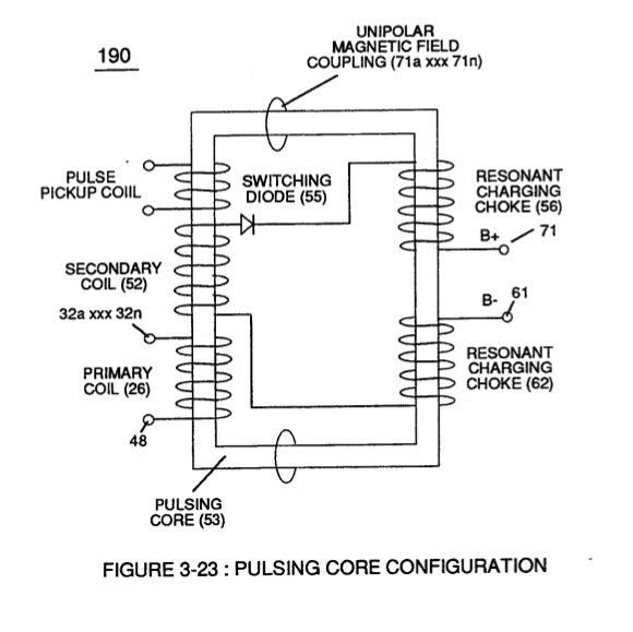
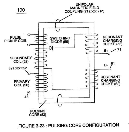
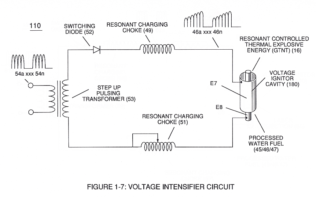
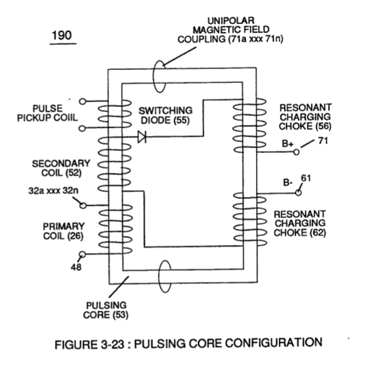
The resultant signal coupling ( 65a xx 65n ) of Figure (3-21) is accomplished since primary coil (26), pulsing core (53), secondary coil (52), switching diode (55), resonant charging choke (56), resonant cavity assembly (170), natural water (68), and variable resonant charging choke (62) forms Voltage Intensifier Circuit (60) of Figure (3-22), as illustrated in Figure (3-22) as to Figure (3-23).
-
pulsing core (53)
Inherently, then, pulsing core (53) of Figure (3-23) aids amp restriction while voltage intensifier circuit (190) is being "tuned" (adjusting pulse train 49a xxx 49n pulse-frequency 63 via pulse frequency generator 70 of figure 3-5) to match the resonant frequency properties of water bath (68) of Figure (3-22), as illustrated in Fuel Cell (120) of Figure (3-24).
Water Fuel Injector (Taper Resonant Cavity Chamber) 5×
-
Adjusting Pulse-train (210a xxx 210n) in such a way as to allow pulse off-time (T2) to be synchronized with collapsing and re-formation of electromagnetic field coupling across pulsing transformer (52/53) to produce unipolar pulse frequency (T1a xxx T1n), as illustrated in (220) of Figure (18) as to Figure (17).
-
Secondary Coil (53)
Pulse on-time (T1) having a predetermined constant voltage level (xxx VL xxx) is adjusted to maximize transference of electromagnetic energy to Secondary Coil (53) during pulsing operations.
-
Secondary Coil (53)
The resultant and newly formed gated Resonant Pulse-train (T1 + T2a xxx T1 + T2n) (58) voltage amplitude (Vo xxx Vn) is, now, attenuated by Sequential Voltage Amplitude Control Circuit (59) once step up Secondary Coil (53) produces a higher voltage level (xxxVL) above incoming pulse-train (210) since Secondary Coil (53) has a greater number of turns of wire.
-
Secondary Coil (53)
The resultant and newly formed gated Resonant Pulse-train (T1 + T2a xxx T1 + T2n) (58) voltage amplitude (Vo xxx Vn) is, now, attenuated by Sequential Voltage Amplitude Control Circuit (59) once step up Secondary Coil (53) produces a higher voltage level (xxxVL) above incoming pulse-train (210) since Secondary Coil (53) has a greater number of turns of wire.
-
Secondary Coil (53)
Sequential Switch Circuit (59) simply switches in and out Booster Pickup Coils (61a xxx 61n) in series electrical hookup with Secondary Coil (53) output to elevate voltage intensity across Resonant Charging Chokes (56/57).
Funneling Effect 1×
-
Secondary Coil (53)
thereby, attenuating voltage amplitude (voltage intensity) beyond Secondary Coil (53) voltage levels (71), as illustrated in (220) of Figure (18).
Tri - Coil Construction 1×
-
Resonant bobbin assembly (503), primary bobbin assembly (504), and secondary bobbin assembly (506), now, make up and structurally forms voltage intensifier (VIC) coil-assembly (530) of Figure (5-6) when electrical steel core material (53) forms a close-loop magnetic induction pathway centrally through and around (VIC) coil-assembly (530), as schematically illustrated in (190) of Figure (3-23) (Memo WFC 422 DA).
Transformer Action 6×
-
Inductance Core (53)
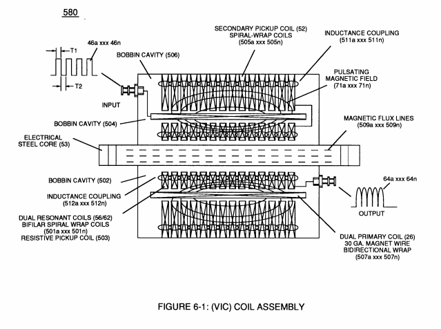
Inductance Core (53) of Figure (6-1) composed of "Grain Oriented" Electrical Steel laminations step up applied Voltage (49) when Magnetic Field Coupling (71) of Figure (7-8) cross over to Secondary Pickup Coil-winding (5 …
-
… -winding (52) which has more turns of wire than Primary Coil- winding (26) by way of "Eddy" currents that induce magnetic flux lines of forces (71a xxx 71n) emanating away from magnetic core material (53) and caused by Primary Coil (26) being electrically energized during pulsing operations (T1a xx T1n), as illustrated in (690) of Figure (7-8).
-
(53) of Figure (6-1)
-
Magnetic Induction (71a - 71n) is determined by Inductance Permeability (μL) of core material (53) along with VIC circuit geometry ability to step up Voltage Potential (Vo - Vn) by way of "Transformer Action", and is expressed in the following equations:
-
Voltage Transformer (26 - 53 - 52)
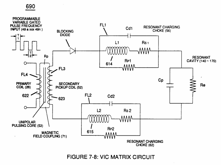
(L1) and (L2) are the inductances of each individual choke coil (56)(62) in series with Secondary Coil (52) Electrical Voltage Potential (700) of Figure (7-9) and being exposed to the same Voltage Transformer (26 - 53 - 52) magnetic field (Rp) with aiding fields,
-
Unipolar Pulsing Core (53)
(M) is the mutual inductance of choke coils (L1/L2) since Transformer Magnetic Field (Rp) is the excitation External Magnetic Field (Rp1/Rp2) by way of Unipolar Pulsing Core (53).
Electron Bounce Phenomenon 3×
-
magnetic pulsing core (53)
High Voltage Potential of Difference (Vo - Vn) (SS' - 617 -RR') is accomplished when magnetic flux lines of force (71a xx 71n) (Rp) emanating away from closed-loop magnetic pulsing core (53) of Figure (190) penetrates Inductance coil-windings (52 - 56 - 62) simultaneously during each and every pulse on-time (T1a xxx T1n) as programmable pulse-train (49a xxx 49n T3 - 49a xxx 49n) is adjus …
-
Voltage Transformer (26 - 53 - 52)
… (L2) are the inductance of each individual choke coil (56)(62) in series with Secondary Coil (52) Electrical Voltage Potential (700) of Figure (7-9) and being exposed to the same Voltage Transformer (26 - 53 - 52) magnetic field (Rp) with aiding fields, (M) is the mutual inductance of choke coils (L1/L2) since Transformer Magnetic Field (Rp) is the excitation External Magnetic Field (Rp1/Rp2) by way of Unipola …
-
Unipolar Pulsing Core (53)
… (Rp) with aiding fields, (M) is the mutual inductance of choke coils (L1/L2) since Transformer Magnetic Field (Rp) is the excitation External Magnetic Field (Rp1/Rp2) by way of Unipolar Pulsing Core (53).