(22) · also written as a run, 22a xxx 22n
Compounding Action
Also written analog signal · analog voltage level · voltage level · analog voltage signal · maximum engine R.P.M · cabling hookup · voltage valves · levels
Where it is first named
Light-gate (9) of Figure (3-10) is mechanically linked to the car acceleration pedal by way of cabling hookup (22).
How it is written
- (22) 7×
- (22a xxx 22n) 3×
- (22a xx) 1×
22a xxx 22n is Meyer's shorthand for a run of the same thing: 22a is the first, 22n the last, and the x's stand for however many lie between. Every stage of the run is this one numeral.
Drawings 53
-
Figure (1-22) · Rocket Propulsion
-
Figure (3-22) · Analog Voltage generator (40)
-
Figure (3-22) · Voltage Amplitude Control Circuit (50)
-
Figure (3-22) · Voltage Intensifier Circuit (60)
-
Figure (3-22) · Voltage Dynamics
-
(330) of Figure (3-37) · Gas Modulator Process
-
Voltage Intensifier Circuit (60) of Figure (3-22) · Gas Processor
-
Carries this number · WFC 422DA - Illustrations
-
Carries this number · WFC 422DA - Illustrations
-
Carries this number · Water Fuel Injection System
-
Carries this number · Electronic Circuit Design
-
Carries this number · Electronic Circuit Design
-
Carries this number · Electronic Circuit Design
-
Carries this number · Electronic Circuit Design
-
Carries this number · Electronic Circuit Design
-
Carries this number · Electronic Circuit Design
-
Carries this number · Electronic Circuit Design
-
(550) of Figure (5-8) · In Application of Usage
-
(550) of Figure (5-8) · Solar Energy Actuator
-
Voltage Intensifier Circuit (60) of Figure (3-22) · Instant Explosion of Water
-
Voltage Intensifier Circuit (620) of Figure (7-1) · Instant Explosion of Water
-
(56/62) of Figure (3-22) · Instant Explosion of Water
-
(56) of Figure (3-22) · Instant Explosion of Water
-
Capacitance Equation (Eq.22) · Resistance (Rs)
-
(750) of Figure (7-14) · Inductance (FL)
-
(750) of Figure (7-14) · Capacitance (Cd)
-
Figure (7-1) · Capacitance (Cd)
-
(620) of Figure (7-1) · Inductance Reactance (Rs - Cd - FL)
-
Choke-Coil (62) of Figure (7-1) · Transformer Action
-
Voltage Graph (750) of Figure (7-14) · Electron Bounce Phenomenon
-
"Resonant Charging Choke" (56) of Figure (7-1) · Propagating Electrical Stress
-
Voltage Intensifier Circuit (60) of Figure (3-22) · Propagating Electrical Stress
-
(60) of Figure (3-22) · Propagating Electrical Stress
-
Voltage Performance Graph (750) of Figure (7-14) · Voltage to Amp Differential Ratio
-
(620) of figure (7-1) · Voltage to Amp Differential Ratio
-
Carries this number · Degaussing Radioactive Material
-
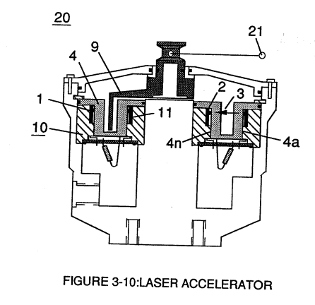
Light-gate (9) integrated with led pickup circuit (10) make up Laser Accelerator assembly (20), as shown in Figure (3-10). · Laser Accelerator Assembly
-
Figure (3-5) · Acceleration Control Circuit (30)
-
Figure (3-13) · Acceleration Control Circuit (30)
-
Figure (3-13) · Acceleration Control Circuit (30)
-
Analog Voltage Circuit (40), as shown in Figure (3-5) · Acceleration Control Circuit (30)
-
Figure (3-5) · Acceleration Control Circuit (30)
-
The figure it sits on · Analog Voltage generator (40)
-
Figure (3-5) · Analog Voltage generator (40)
-
Laser Accelerator (20) of Figure (3-10) · Laser Distributor
-
Figure (3-5) · Laser Distributor
-
The figure it sits on · WFC 422DA - Illustrations
-
The figure it sits on · WFC 422DA - Illustrations
-
The figure it sits on · WFC 422DA - Illustrations
-
The figure it sits on · WFC 422DA - Illustrations
-
3-5 Outer Core Bobbin · Voltage Intensifier Coil Assembly
-
3-13 Flat Seal · Voltage Intensifier Coil Assembly
-
3-14 WFC Voltage Ignition Wire · Voltage Intensifier Coil Assembly
Where it is named · 11
Laser Accelerator Assembly 1×
-
cabling hookup (22)
Light-gate (9) of Figure (3-10) is mechanically linked to the car acceleration pedal by way of cabling hookup (22).
Analog Voltage generator (40) 8×
-
analog voltage signal (22)
The generated digital signal (19) being electrically transmitted from accelerated control circuit (30) of Figure (3-5) is, now, electronically detected, translated, and converted into a analog voltage signal (22) which is continuously proportionate to input signal (19) by Analog Voltage Generator Circuit (40) of Figure (3-5).
-
analog signal (22)
The newly formed analog signal (22) of Figure (3-14) is a voltage level signal that varies continuously in both time and amplitude to produce a voltage level which is directly proportional to the physical change in pulse train (100 xxx 16n) of Figure (3-13).
-
analog signal (22)
Widening pulse width to stop-position (17a xxxx 17n) of Figure (3-13) causes analog signal (22) to increase to higher voltages levels; whereas, analog voltage level (22) drops (become lower in value) in voltage level when pulse width decreases to start-position (17a).
-
analog voltage level (22)
Widening pulse width to stop-position (17a xxxx 17n) of Figure (3-13) causes analog signal (22) to increase to higher voltages levels; whereas, analog voltage level (22) drops (become lower in value) in voltage level when pulse width decreases to start-position (17a).
-
voltage level (22a xx)
The resultant and varied voltage level (22a xx) varies smoothly over a continuous range of voltage valves (22a xxx 22n) rather than in discrete steps, as illustrated in linear graph (23) of Figure (3-14).
-
voltage valves (22a xxx 22n)
The resultant and varied voltage level (22a xx) varies smoothly over a continuous range of voltage valves (22a xxx 22n) rather than in discrete steps, as illustrated in linear graph (23) of Figure (3-14).
-
maximum engine R.P.M (22a xxx 22n)
Analog circuit (40) also calibrates both engine idling speed (22ax) and maximum engine R.P.M. (22a xxx 22n) by adjusting and maintaining a predetermined or given low (24) and high voltage levels respectively, as further illustrated in Figure (3-14).
-
levels (22a xxx 22n)
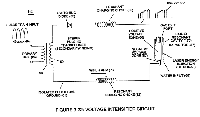
Voltage valves or levels (22a xxx 22n) simply controls the applied voltage potential across Resonant Cavity Assembly (120) of Figure (3-22) through voltage amplitude control circuit (50) of Figure (3-5) which is is electrically linked to primary coil (26) of Figure (3-22) of Voltage Intensifier Circuit (60) of Figure (3-5).
Resonant Propagation 2×
-
Compounding Action (22)
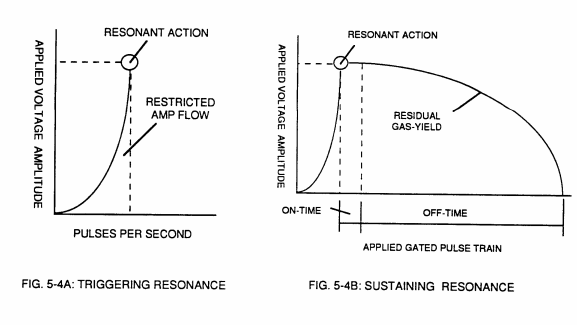
Compounding Action (22) (deflection of electrical charged particles) by way of voltage stimulation aids Resonant Action by superimposing particle impact onto to the Electrical Polarization Process (160).
-
Compounding Action (22)
Resonant Action (21), Compounding Action (22), Laser Injection (17). and Energy Pumping Action (520), Now, allows the production of hydrogen and oxygen gases from water in geometrical progression to set up Hydrogen Fracturing Process (90). as illustrated in Figure (5-4C) as to Figure (5-5).