(Vpp) · also written as a run, Vppa xxx Vppn
Voltage Peak Potential
Also written Negative Voltage Peak Potential · Positive Voltage Peak Potential · Applied Voltage Peak Potential · Peak Voltage Potential · Voltage Peak-Potential · Voltage Amplitude Peak Level · Voltage-Pulse Amplitudes · Voltage Pulse Potential and 3 more
Where it is first named
… s to the Voltage Burst-Frequency (49a xxx 49n) as to Voltage Peak Excursion Point "P" at the height of Unipolar Voltage Pulse Wave (583/602) which, in turns, determines maximum Voltage Peak-Potential (Vpp) at any given time during each Voltage Pulsing Cycle (Vpa/Vpb).
How it is written
- (Vpp) 12×
- (+Vpp) 1×
- (-Vpp) 1×
- (49-Vpp-Vgpa xxx 49-Vpp-Vgpn) 1× with (Vgp) Opposite Voltage Potential
- (Vppa xxx Vppn) 1×
- (+Vpp / - Vpp) 1×
- (+Vpp/- Vpp) 1×
Vppa xxx Vppn is Meyer's shorthand for a run of the same thing: Vppa is the first, Vppn the last, and the x's stand for however many lie between. Every stage of the run is this one numeral.
Drawings 40
-
Figure (3-21) · Voltage Amplitude Control Circuit (50)
-
Figure (3-21) · Voltage Intensifier Circuit (60)
-
The figure it sits on · Voltage Dynamics
-
The figure it sits on · Gas Processor
-
The figure it sits on · WFC 422DA - Illustrations
-
The figure it sits on · Differential Air-Gas Inlet Control
-
Figure (4-7) · Water Fuel Injection System - Page 3
-
Figure (5-8) · Energy Pumping Action
-
(550) of Figure (5-8) · In Application of Usage
-
(550) of Figure (5-8) · Covalent Switch-Off
-
(7) of Figure (5-8) · Energy Aperture of the Atom
-
(550) of Figure (5-8) · Solar Energy Actuator
-
(90) of Figure (4-7) · Capacitance Reactance
-
(780A) Figure (8-2) · 8-2 - Traveling Voltage Wave-Guides
-
(770) of Figure(8-1) · 8-2 - Traveling Voltage Wave-Guides
-
Figure (8-2) · 8-2 - Traveling Voltage Wave-Guides
-
(770) of Figure (8-1) · 8-3 - Electrical Voltage-Pulse Wave-Transmission
-
(770 A) of Figure (8-1) · 8-4 - State Space (Sp)
-
(770 B) of Figure (8-1) · 8-4 - State Space (Sp)
-
(780 B) of Figure (8-2) · 8-4 - State Space (Sp)
-
(780 A/B/C) of Figure (8-2) · 8-4 - State Space (Sp)
-
(585) of Figure (8-1) · 8-4 - State Space (Sp)
-
(550 of Figure 5-8) · 8-4 - State Space (Sp)
-
Resonant Cavity (90) of Figure (4-7) · 8-5 - Energy Vectoring (Ev)
-
(770A) of Figure (8-1) · 8-5 - Energy Vectoring (Ev)
-
Clipped Voltage Wave-form (780C) of Figure (8-2) · 8-5 - Energy Vectoring (Ev)
-
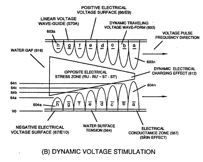
(612) of Figure (8-1) · 8-5 - Energy Vectoring (Ev)
-
The figure it sits on · 8-6 - VIC Voltage Sync-Pulse Circuit
-
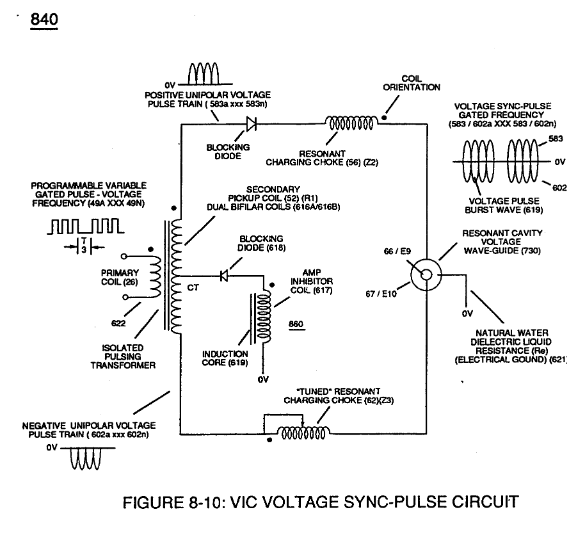
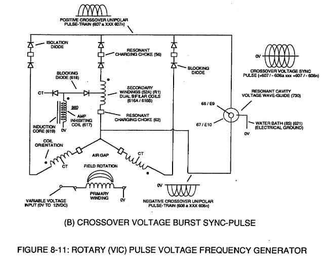
(850) of Figure (8-11) · 8-6 - VIC Voltage Sync-Pulse Circuit
-
The figure it sits on · WFC 427 Illustrations
-
The figure it sits on · WFC 427 Illustrations
-
The figure it sits on · WFC 427 Illustrations
-
"Electrovalent Switch-off" phenomenon (550) of Figure (5-8) · WFC Exhaust Air Reclaimer
-
"Voltage Tickling of State Space" (770A) of Figure (8-1) · WFC Exhaust Air Reclaimer
-
"Voltage Tickling of State Space" (770B) of Figure (8-1) · WFC Exhaust Air Reclaimer
-
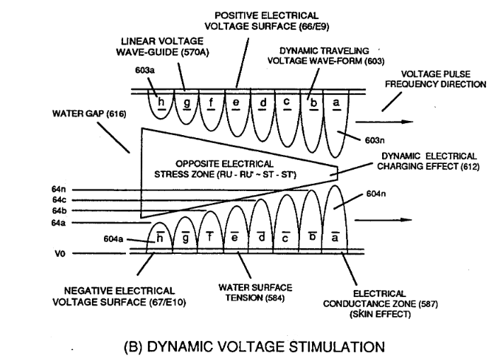
Dynamic Electrical Charging Effect (612) of Figure (8-1) · Propagating Electrical Stress
-
hydrogen energy aperture (7) of (550) of Figure (5-8) · Optical Thermal Lens
-
The figure it sits on · Quartz Tube Configuration & Operational Parameters
-
... establishing variable Dynamic Electrical Charging Effect (612). · Quartz Tube Configuration & Operational Parameters
-
The figure it sits on · Degaussing Radioactive Material
Where it is named · 18
8-4 - State Space (Sp) 5×
-
Voltage Peak-Potential (Vpp)
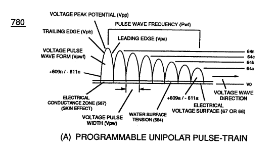
… s to the Voltage Burst-Frequency (49a xxx 49n) as to Voltage Peak Excursion Point "P" at the height of Unipolar Voltage Pulse Wave (583/602) which, in turns, determines maximum Voltage Peak-Potential (Vpp) at any given time during each Voltage Pulsing Cycle (Vpa/Vpb).
-
Peak Voltage Potential (Vpp)
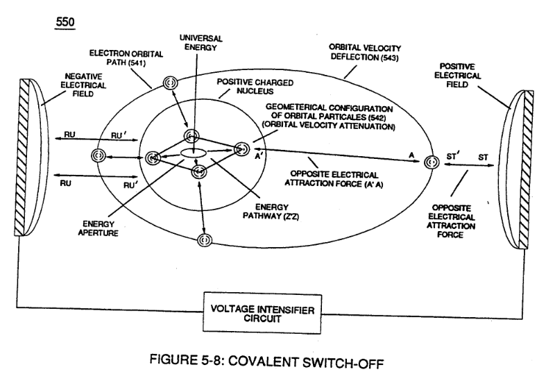
Electrical Attraction Force intensity (RR' - SS' as to RU/RU' - ST/ST' as to 550 of Figure 5-8) at Peak Voltage Potential (Vpp) is either increasing or decreasing or remaining constant as to Voltage Peak Excursion Point "P" trace-position which scans the exact Pulse Wave-Form (66- 583/67-602) being produced, as illustrated in (780B) of Figure (8-2).
-
Peak Voltage Potential (Vpp)
… pace" is referred to as “Dynamic State Space;" whereas, "Static State Space" exists when Voltage Excursion Point "P" remains constant during a precise period of space-time at Peak Voltage Potential (Vpp) forming clipped Voltage Pulse Wave-form (Vcwf) during Voltage Pulse Shaping by way of Programmable Pulsing Circuit (WFC project 422DA/423DA) electrically interfaced with VIC Matrix Circuit (690), as …
-
Peak Voltage Potential (Vpp)
… o formation of Voltage Peak Curve (Vpc); wherein, Static State Space allows Opposite Attraction Force (RR' -SS') to remain at constant electrical intensity (RR' - SS' cei) when Peak Voltage Potential (Vpp) is clipped in forming Arc-Line (Val), as illustrated in (780C) of Figure (8-2).
-
Voltage Peak-Potential (Vpp)
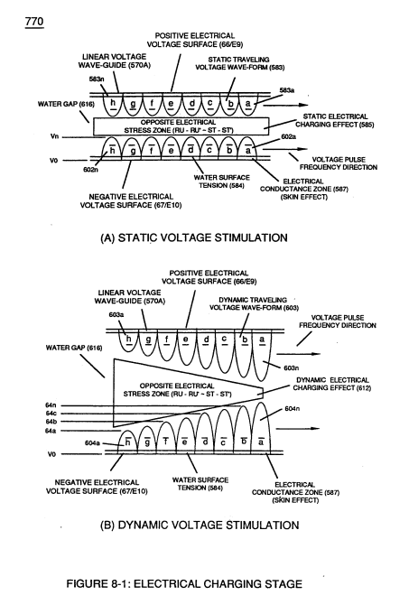
… of Particle Oscillation (Poe) as a Energy-Generator (EGpo), if Voltage Arc Line (Val) length is extended while Voltage Amplitude (xx 64a - 64b - 64c - Vn) is adjusted to higher Voltage Peak-Potential (Vpp) then greater atomic interaction (585) of Figure (8-1) (see WFC memo 424 titled Atomic Energy Balance of Water, once again) occurs when particle oscillation (Poe) of deflection of atomic mass (see 550 …

8-5 - Energy Vectoring (Ev) 2×
-
Voltage Pulse Potential (Vpp)
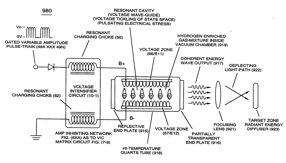
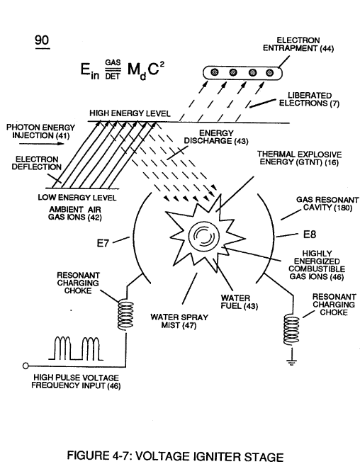
The "mode of operability" of determining the "Operational Parameters" of adjusting the thermal explosive energy (gtnt) exiting from nozzle-port (32) of Figure (4-5) as to (40) of Figure (4-2) is directly related to the characteristics of the applied Voltage Pulse Potential (Vpp) Wave-form (s) (Vpwt) and the geometrical configuration of Resonant Cavity (90) of Figure (4-7) as to (730) of Figure (7-12).
-
Voltage Peak Potential (Vpp)
On the other hand, Progressive Voltage Sync-Wave (+609 / - 611) (609/611a xxx 609/611n) of Figure (780A) of Figure (8-2) encourages Dynamic Voltage Stimulation (Dvs) since Voltage Peak Potential (Vpp) increases as Voltage Sync-Wave Front (a to b to c and so on) advances in the number of Unipolar Voltage Pulse (s) (Vwp), as illustrated in Figure (3-21) ... …
8-6 - VIC Voltage Sync-Pulse Circuit 7×
-
Voltage-Pulse Amplitudes (+Vpp/- Vpp)
… all, forming Voltage Pulse Burst Wave (619) as to Unipolar Pulse-Train (780A), Crossover Unipolar Pulse-Train (780B), and Clipped Unipolar Pulse Train (780C) as to Traveling Voltage Wave-Action (770) of Figure (8-1) of opposite voltage polarity (+/-) of equal Voltage-Pulse Amplitudes (+Vpp/- Vpp) are zero reference to electrical ground state (0V) by placing Amp Inhibitor Circuit (860) (Amp Inhibiting Coil 617, Blocking Diode 618, and Magnetic Induction Core 619) between electrical ground (0V) …
-
By doing so, Balance Phasing of opposite voltage intensity (+Vpp / - Vpp) is accomplished without experiencing current influxing caused by differential variances where Negative Voltage Peak Potential (-Vpp) is less than Positive Voltage Peak Potential (+Vpp) or Vise Versa ... …
-
Negative Voltage Peak Potential (-Vpp)
By doing so, Balance Phasing of opposite voltage intensity (+Vpp / - Vpp) is accomplished without experiencing current influxing caused by differential variances where Negative Voltage Peak Potential (-Vpp) is less than Positive Voltage Peak Potential (+Vpp) or Vise Versa ... …
-
Positive Voltage Peak Potential (+Vpp)
… ensity (+Vpp / - Vpp) is accomplished without experiencing current influxing caused by differential variances where Negative Voltage Peak Potential (-Vpp) is less than Positive Voltage Peak Potential (+Vpp) or Vise Versa ... allowing Inductor Resonant Choke Coils Electromagnetic Fields Intensity (+Z2 / -Z3) to be, in turn, free of Electromagnetic variances of intensity (Z2 - Z3).
-
Unipolar Voltage Pulse (Vpp)
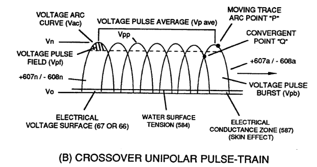
… oltage Wave-Form (780B) as to (780C) of Figure (8-2) is generally utilized by not allowing Convergent Point "Q" of Figure (780B) to reach Electrical Ground Point (0V) when each Unipolar Voltage Pulse (Vpp) is electrical energized in phase-distance relationship to cause the trailing edge (Vpb) of the first Voltage-Pulse (Vppl) to meet the uprising leading edge (Vpa) of the second Voltage Pulse Wave (Vpp …
-
Voltage Peak Wave (Vppa xxx Vppn)
… -Pulse (Vppl) to meet the uprising leading edge (Vpa) of the second Voltage Pulse Wave (Vpp2) at a distance above ground state (OV) determined by the Space-movement of the reforming Voltage Peak Wave (Vppa xxx Vppn) within Voltage Pulse Width (TI), as illustrated in Rotary Crossover Voltage Sync-Pulse Circuit (850) of Figure (8-11) where each VIC Pickup Coils (52A-52B -52C) are axially spaced 120· apart to caus …
-
Voltage Amplitude Peak Level (Vpp)
… lse Circuit (850) of Figure (8-11) where each VIC Pickup Coils (52A-52B -52C) are axially spaced 120· apart to cause Convergent Point "Q" to be located 1/3 the height of Voltage Amplitude Peak Level (Vpp), as an example.
Quartz Tube Configuration & Operational Parameters 2×
-
Voltage Peak potential (Vpp)
… ctive State" (As) and then back again to "Quiescent State" (Qs) once applied unipolar pulse-wave (583/602) goes through Voltage Pulsing Cycle (Vpwf) from "Ground State" (Gs) to Voltage Peak potential (Vpp) (780) of Figure (8-2A) and then returns to "Ground State" (Gs) for continued repetitive Voltage-Pulsing (583/602a xxx 583/602n)
-
Voltage Peak Potential (Vpp)
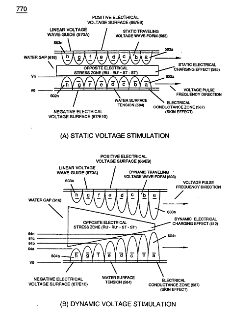
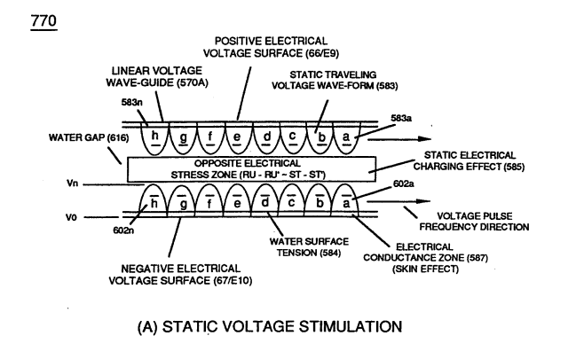
Static Voltage Stimulation (770) of Figure (8-1A) is where Voltage Peak Potential (Vpp) remains constant during Voltage Pulse Formation (VpbNpa) to keep reforming Flex-Density Potential (Fdpa xxx Fdpn) from going beyond a certain point away from Static State of Equilibrium (Esse)
A Technique Called "Easer" 2×
-
Applied Voltage Peak Potential (Vpp)
Together but in separate variable forms, Applied Voltage Peak Potential (Vpp),Voltage Pulse Cycling (49a xxx 49n), and Opposite Voltage Potential (Vgpa xxx Vgp) forming Voltage Sync-Pulse (49-Vpp-Vgpa xxx 49-Vpp-Vgpn) determines the energy-intensity (Eie) of the coherent-beam (919).
-
Voltage Sync-Pulse (49-Vpp-Vgpa xxx 49-Vpp-Vgpn)
Together but in separate variable forms, Applied Voltage Peak Potential (Vpp),Voltage Pulse Cycling (49a xxx 49n), and Opposite Voltage Potential (Vgpa xxx Vgp) forming Voltage Sync-Pulse (49-Vpp-Vgpa xxx 49-Vpp-Vgpn) determines the energy-intensity (Eie) of the coherent-beam (919).