(45) · also written as a run, 45a xxx 45n
Non-Combustible Gases
Also written gated pulse duty cycle · noncombustible gases · gated duty pulse · fluid flow rate · fluid-mediums · fluid-medium · gated pulse
Where it is first named
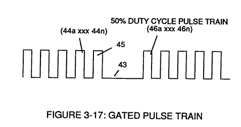
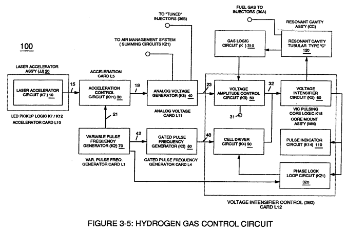
Gated Pulse Circuit (80) of Figure (3-5) switches "off' and "on" sections of incoming clock signal (42) to form gated pulse (45) which is, in turn, duplicated in succession to produce gated pulse train (46a xxx 46n) of Figure (3-17).
How it is written
- (45) 10×
- (45a xxx 45n) 3×
- (45 / 46 / 47) 3× with (46) Ionized Ambient Air Gases, (47) Water Mist
- (45a xxx) 2×
- (47 / 45 / 46) 1× with (47) Water Mist, (46) Ionized Ambient Air Gases
- (47 / 45/ 46) 1× with (47) Water Mist, (46) Ionized Ambient Air Gases
- (47/45/46) 1× with (47) Water Mist, (46) Ionized Ambient Air Gases
- (45 / 46/ 47) 1× with (46) Ionized Ambient Air Gases, (47) Water Mist
45a xxx 45n is Meyer's shorthand for a run of the same thing: 45a is the first, 45n the last, and the x's stand for however many lie between. Every stage of the run is this one numeral.
Drawings 52
-
Carries this number · Gated Pulse Frequency generator (80)
-
Together pulse train (44a xxx 44n) and pulse off-time (43) forms gated pulse duty cycle (45). · Gated Pulse Frequency generator (80)
-
... thereby, extracting contaminates (144a xxx 144n) from water bath (68) · Impurity Extraction Process
-
Water Fuel Injector Plug (40) of Figure (4-2) · Operational Parameters
-
Carries this number · WFC 422DA - Illustrations
-
Carries this number · WFC 422DA - Illustrations
-
Carries this number · Water Fuel Injection System
-
3-8 Multi-Coil Spool · Voltage Intensifier Coil Assembly
-
Carries this number · Voltage Intensifier Coil Assembly
-
Carries this number · Voltage Intensifier Coil Assembly
-
Carries this number · Differential Air-Gas Inlet Control
-
(170) of Figure (13) · Water Fuel Injector (Taper Resonant Cavity Chamber)
-
(170) of Figure (13) · Water Fuel Injector (Taper Resonant Cavity Chamber)
-
...positive charged gas particles (81a xxx 81n) being directed to and attached to negative charged oxygen atom (76) of water molecule (47); · Water Fuel Injector (Taper Resonant Cavity Chamber)
-
Fluid Displacement Pump (170) of Figure (13) · Water Fuel Injector (Taper Resonant Cavity Chamber)
-
(70) of Figure (3B) · Water Fuel Injector (Taper Resonant Cavity Chamber)
-
Electronic Circuit (110) of Figure (7) · Water Fuel Injector (Taper Resonant Cavity Chamber)
-
Carries this number · Funneling Effect
-
Figure (4-4) · Water Fuel Injection System - Page 1
-
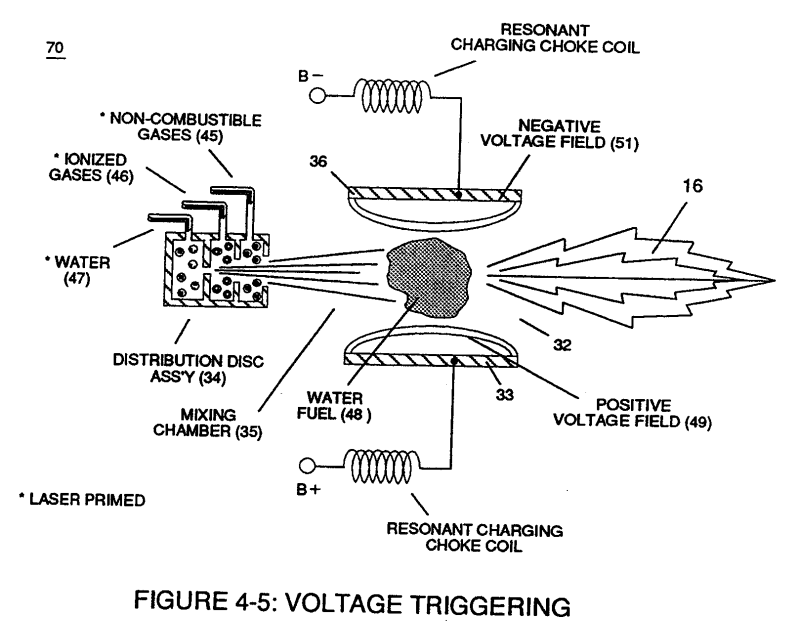
Figure (4-5) · Water Fuel Injection System - Page 1
-
Figure (4-2) · Water Fuel Injection System - Page 1
-
Figure (4-8) · Water Fuel Injection System - Page 2
-
Figure (4-10) · Water Fuel Injection System - Page 2
-
Figure (4-9) · Water Fuel Injection System - Page 2
-
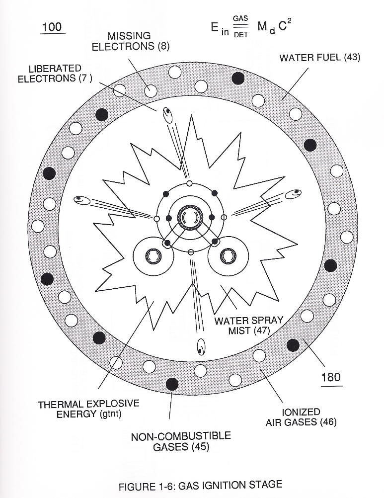
but, also prevents electron flow into destabilizing gas process (180), as so illustrated in Figure (4-5). · Water Fuel Injection System - Page 3
-
which simply uses Water Fuel Management (WFMS) System fluid-metering system (40) to control gas ignition (16), as illustrated in (40) of Figure (4-2). · Water Fuel Injection System - Page 4
-
Carries this number · In Application of Usage
-
(100) of Figure (4-8) · In Application of Usage
-
(110) of Figure (4-9) · In Application of Usage
-
Voltage Triggering Process (70) of Figure (4-5) · Voltage Intensifier Coil-Assembly
-
(100) of Figure (4-8) · Voltage Intensifier Coil-Assembly
-
(16) of Figure (4-5) · Resistance (Rs)
-
(110) of Figure (4-9) · Resistance (Rs)
-
(100) of Figure (4-8) · Capacitance Reactance
-
Figure (4-5) · Capacitance Reactance
-
Figure (4-5) · 8-5 - Energy Vectoring (Ev)
-
(40) of Figure (4-2) · 8-5 - Energy Vectoring (Ev)
-
Voltage Intensifier Circuit (110) of Figure (4-9) · WFC Exhaust Air Reclaimer
-
Blocking Diode (52) of Figure (4-9) · Propagating Electrical Stress
-
The figure it sits on · Electronic Circuit Design
-
The figure it sits on · Electronic Circuit Design
-
The figure it sits on · Electronic Circuit Design
-
(220) of Figure (18) · Water Fuel Injector (Taper Resonant Cavity Chamber)
-
The figure it sits on · Water Fuel Injector (Taper Resonant Cavity Chamber)
-
The Following Page 1-7 was not available · Water Fuel Injector (Taper Resonant Cavity Chamber)
-
thereby, attenuating voltage amplitude (voltage intensity) beyond Secondary Coil (53) voltage levels (71), as illustrated in (220) of Figure (18). · Funneling Effect
-
The figure it sits on · WFC 427 Illustrations
-
Figure (10-3 A/B) · Propagating Electrical Stress
-
The figure it sits on · WFC 429 - Illustrations
-
The figure it sits on · WFC 429 - Illustrations
-
The figure it sits on · WFC 429 - Illustrations
-
The figure it sits on · Wobbling Effect
Where it is named · 24
Gated Pulse Frequency generator (80) 3×
-
gated pulse (45)
Gated Pulse Circuit (80) of Figure (3-5) switches "off' and "on" sections of incoming clock signal (42) to form gated pulse (45) which is, in turn, duplicated in succession to produce gated pulse train (46a xxx 46n) of Figure (3-17).
-
gated pulse duty cycle (45)
Together pulse train (44a xxx 44n) and pulse off-time (43) forms gated pulse duty cycle (45).
-
gated duty pulse (45)
Newly formed gated duty pulse (45) is proportional to the physical change in pulse train (44a xxx 44n) when circuit (80) is adjusted for calibration purposes.
Water Fuel Injection System 9×
-
non-combustible gases (45)
Secondly, ionized air gases (46a xxx 46n) of Figure (3A) (laser primed ambient air gases having missing electrons) produced by Ambient Air Ionizer (80) of Figure (4) as to Figure (1) and non-combustible gases (45) of Figure (3A) are intermixed with expelling water mist (47a xxx 47n) to form Water-fuel mixture (48) by way of gas mixing disc (34) of Figure (3B) as to (30) of Figure (2A);
-
non-combustible gases (45)
To ensure proper energy-flame projection and subsequent energy-flame stability, constant placement water pump (170) causes and allows ionized ambient air gases (46), non-combustible gases (45), and water (47) to be displaced under static pressure up to and beyond 125 psi respectively.
-
Energy-Flame temperature is regulated by controlling the volume flow-rate of each fluid mediums (47 / 45/ 46) in direct relationship to applied voltage intensity (33 /36), as further stated in Figure (2B) as to Figure (3B).
-
To elevate Energy-flame-temperature still further, help increase fluid-displacement (46/47) while maintaining or reducing the volume flow rate of non-combustible gases (45) during an increase of applied voltage amplitude (Vo x Vn) of Figure (32) as to Voltage Intensifier Circuit (110) of Figure (7) and Electron Extraction Circuit (120) of Figure (8).
-
To lower Energy-flame temperature simply increase the amount of non-combustible gas (45a xxx) or reduced the fluid flow rate (45 / 46/ 47)) uniformly while lowering pulse voltage amplitude (xxx Vo).
-
To lower Energy-flame temperature simply increase the amount of non-combustible gas (45a xxx) or reduced the fluid flow rate (45 / 46/ 47)) uniformly while lowering pulse voltage amplitude (xxx Vo).
-
To establish a predetermined or given Energy-flame temperature adjust fluid-medium (45 / 46 / 47)) and applied voltage amplitude (Vo xxx) independent of each other to obtain the desired results.
-
Injected non-combustible gases (45a xxx 45) retards and controls the combustion rate of the Hydrogen Fracturing Process (100) of Figure (6) during gas-ignition.
-
non-combustible gases (45a xxx 45n)
especially when ionized ambient air gases (46a xxx 46n) and non-combustible gases (45a xxx 45n) are intermixed with water supply (47) prior to entering.
Water Fuel Injector (Taper Resonant Cavity Chamber) 2×
-
non-combustible gases (45)
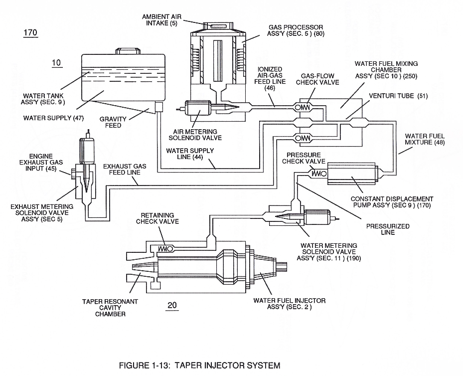
In like manner, water supply (10) of Figure (170), non-combustible gases (45) (Engine Exhaust gases), and ambient air ionized gases (46) (air gases having missing electrons) are uniformly intermixed when moving into, passing through and beyond fluid mixing chamber (250) of Figure (13) by way of venturi tube-cavity (51)...
-
allowing water fuel mixture (47/45/46) (48) to be particle aligned by opposite electrostatically charged atoms
Water Fuel Injection System - Page 1 1×
-
non-combustible gases (45)
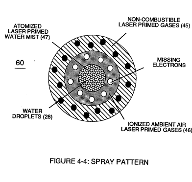
Secondly, ionized air gases (46a xxx 46n) of Figure (4-4) (laser primed ambient air gases having missing electrons) produced by Ambient Air Ionizer (80) of Figure (4-6) as to Figure (4-1) and non-combustible gases (45) of Figure (4-4) are intermixed with expelling water mist (47a xxx 47n) to form Water-fuel mixture (48) by way of gas mixing disc (34) of Figure (4-5) as to (30) of Figure (4-2);
Water Fuel Injection System - Page 2 6×
-
noncombustible gases (45)
To ensure proper energy-flame projection and subsequent energy-flame stability, constant displacement water pump (170) causes and allows ionized ambient air gases (46), noncombustible gases (45), and water (47) to be displaced under static pressure up to and beyond 125 lbs psi, respectively.
-
fluid-mediums (47 / 45 / 46)
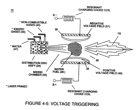
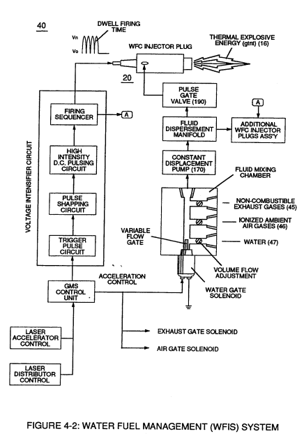
Energy-Flame temperature is regulated by controlling the volume flow-rate of each fluid-mediums (47 / 45 / 46) in direct relationship to applied voltage intensity (33 / 36), as further illustrated in Figure (4-2) as to Figure (4-5).
-
non-combustible gases (45)
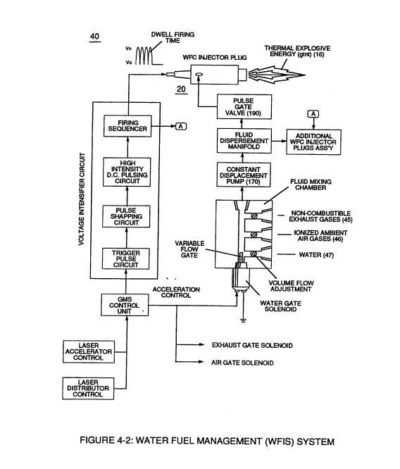
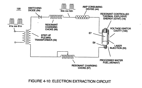
To elevate Energy-flame-temperature still further, simply increase fluid-displacement (46/47) while maintaining or reducing the volume flow rate of non-combustible gases (45) during an increase of applied voltage amplitude (V0 xxx Vo) of Figure (4-2) as to Voltage Intensifier Circuit (110) of Figure (4-9) and Electron Extraction Circuit (120) of Figure (4-10).
-
non-combustible gases (45a xxx)
To lower Energy-flame temperature simply increase the amount of non-combustible gases (45a xxx) or reduced the fluid flow rate (45 / 46 / 47) uniformly while lowering pulse voltage amplitude (xxx V0).
-
fluid flow rate (45 / 46 / 47)
To lower Energy-flame temperature simply increase the amount of non-combustible gases (45a xxx) or reduced the fluid flow rate (45 / 46 / 47) uniformly while lowering pulse voltage amplitude (xxx V0).
-
fluid-medium (45 / 46 / 47)
To establish a predetermined or given Energy-flame temperature adjust fluid-medium (45 / 46 / 47) and applied voltage amplitude (V0 xxx) independent of each other to obtain the desired results.
Water Fuel Injection System - Page 3 1×
-
non-combustible gases (45a xxx 45n)
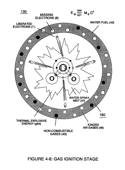
Injected non-combustible gases (45a xxx 45n) retards and controls the combustion rate of the Hydrogen Fracturing Process (100) of Figure (4-8) during gas-ignition.
Water Fuel Injection System - Page 4 1×
-
non-combustible gases (45a xxx 45n)
... especially when ionized ambient air gases (400 xxx 46n) and non-combustible gases (45a xxx 45n) are intermixed with water supply (47) prior to entering Water Fuel Injector Plug (20/30), as illustrated in (40) of Figure (4-2) as to (10) of Figure (4-1).
Capacitance Reactance 1×
-
which, when occurring at gas exit port (32) of Figure (4-5), spark-ignites expanding water gas-fuel (45/46/47) of Figure (4-5) during water inject cycle (70) of Figure (4-5)