(41) · also written as a run, 41a xxx 41n
Liquid Spray Path
Also written pulse train · water spray ports · clock signal
Where it is first named
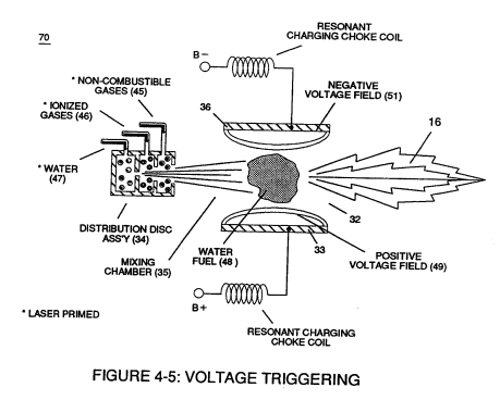
Pulse on-time (37) and pulse off-time (38) are equally displaced to form duty pulse (39) which is duplicated in succession to produce pulse train (41) of Figure (3-16).
How it is written
- (41) 6×
- (41a xxx 41n) 5×
41a xxx 41n is Meyer's shorthand for a run of the same thing: 41a is the first, 41n the last, and the x's stand for however many lie between. Every stage of the run is this one numeral.
Drawings 32
-
Carries this number · Spark-Ignition Tube
-
Figure (3-16) · Acceleration Control Circuit (30)
-
Figure (3-16) · Variable Pulse Frequency Generator (70)
-
(330) of Figure (3-37) · Gas Modulator Process
-
Carries this number · Laser Distributor
-
burn-rate (330) of Figure (3-37) · Diesel Application
-
Carries this number · WFC 422DA - Illustrations
-
Carries this number · WFC 422DA - Illustrations
-
Carries this number · WFC 422DA - Illustrations
-
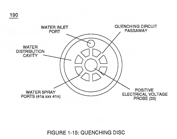
Quenching Disc Structure (190) of Figure (15) · Water Fuel Injector (Taper Resonant Cavity Chamber)
-
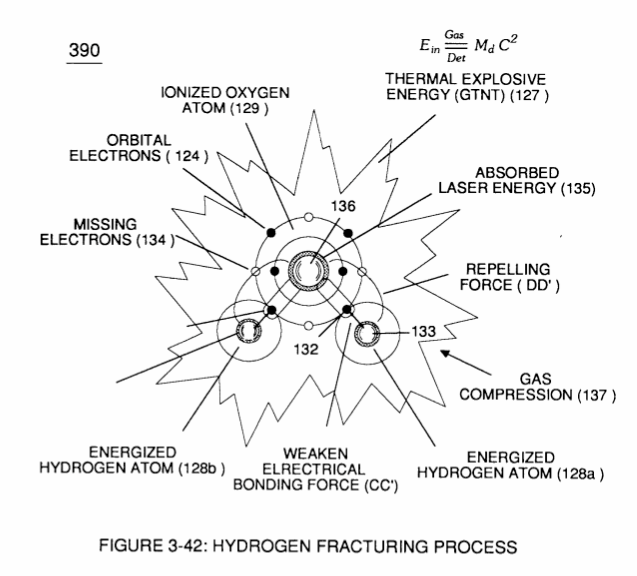
(390) of Figure (41) · Water Fuel Injector (Taper Resonant Cavity Chamber)
-
Figure (4-7) · Water Fuel Injection System - Page 3
-
Figure (5-5) · Resonant Propagation
-
(85) of Figure (3-26) · In Application of Usage
-
Carries this number · Illustrations
-
(90) of Figure (5-5) · Capacitance Reactance
-
(90) of Figure (4-7) · Capacitance Reactance
-
... causing "electron clustering" (641a xxx 641n) to take place within Copper Wire Zone (52) during pulse on- time (T1) · Electron Bounce Phenomenon
-
(90) of Figure (5-5) · 8-2 - Traveling Voltage Wave-Guides
-
Resonant Cavity (90) of Figure (4-7) · 8-5 - Energy Vectoring (Ev)
-
Carries this number · Wobbling Effect
-
Figure (3-5) · Acceleration Control Circuit (30)
-
Analog Voltage Circuit (40), as shown in Figure (3-5) · Acceleration Control Circuit (30)
-
Figure (3-5) · Acceleration Control Circuit (30)
-
Figure (3-5) · Analog Voltage generator (40)
-
Figure (3-5) · Laser Distributor
-
The figure it sits on · WFC 422DA - Illustrations
-
3-5 Outer Core Bobbin · Voltage Intensifier Coil Assembly
-
3-16 Mount Bar · Voltage Intensifier Coil Assembly
-
The figure it sits on · Electronic Circuit Design
-
thereby, attenuating voltage amplitude (voltage intensity) beyond Secondary Coil (53) voltage levels (71), as illustrated in (220) of Figure (18). · Funneling Effect
-
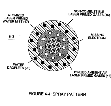
Figure (4-4) · Water Fuel Injection System - Page 1
Where it is named · 11
Variable Pulse Frequency Generator (70) 2×
-
pulse train (41)
Pulse on-time (37) and pulse off-time (38) are equally displaced to form duty pulse (39) which is duplicated in succession to produce pulse train (41) of Figure (3-16).
-
clock signal (41a xxx 41n)
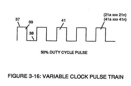
Circuit (70) also produces another independent and separate clock signal (41a xxx 41n) which is electrically transmitted to and become incoming clock signal (42) for Gated Pulse Frequency Generator Circuit (80) of Figure (3-5).
Gated Pulse Frequency generator (80) 1×
-
pulse train (41a xxx 41n)
Pulse train (44a xxx 44n) is exactly the same as pulse train (41a xxx 41n) and its established pulse frequency (number of pulse cycles per unit of time) changes uniformly when pulse generator (70) of Figure (3-5) is calibrated and adjusted for system operations.
Water Fuel Injection System 3×
-
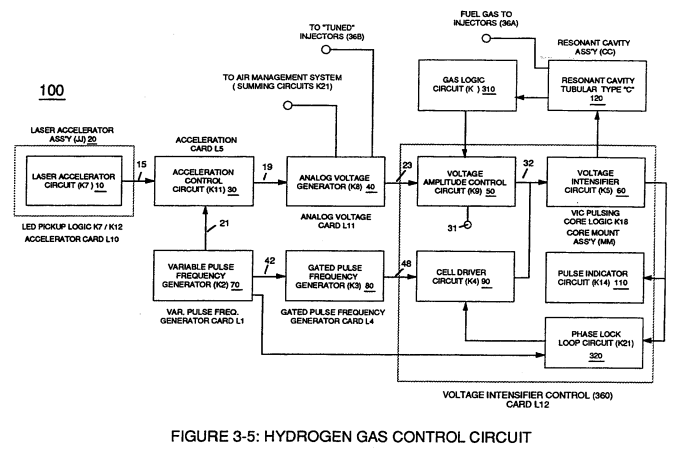
First water mist (47) of Figure (1-3A) is injected into fuel-mixing chamber (35) of Figure (3B) by way of water spray ports (41a xxx 41n) of Figure (3A);
-
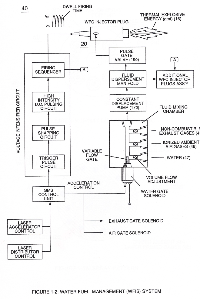
… not only performs electrical polarization process (160) of Figure (25) undergoing Dielectric Resonant (240) of Figure (30); but, also sets up and triggers Hydrogen Fracturing Process (390) of Figure (41) as to Figure (6) under control state (on demand) via electrical-static spark ignition (49 / 51) of Figure (3B)....releasing thermal explosive energy (gtnt) (16) passing beyond gas exit port (32) of F …
-
liquid spray path (41)
Energy-Flame density is enhanced and sustained by causing ionized gases (46a xxx 46n) of spray port (42) to be deflected into liquid spray path (41), together water mist (47) and ionized air (46) are, now, directed toward and deflected through non-combustible gas spray path producing uniformed water-fuel mixture (48), as illustrated in Figure (3B).
Water Fuel Injector (Taper Resonant Cavity Chamber) 3×
-
The resultant water fuel-mixture (48) is, now, pressurized up to and beyond 125 lbs of fluid-pressure by Fluid Displacement Pump (170) of Figure (13), as before, to cause and form water fuel-droplets (48a xxx 48n) when water fuel (48) enters into, passes through and beyond spray ports (41a xxx 41n) forming Quenching Disc Structure (190) of Figure (15).
-
which, in turns, ejects a greater number of electrons while preventing the formation of the water molecule (390) of Figure (41) (WFC Memo 422 DA) during thermal gas-ignition (180) of Figure (14).
-
(390) of Figure (41)
Water Fuel Injection System - Page 1 1×
-
water spray ports (41a xxx 41n)
First water mist (47) of Figure (4-4) is injected into fuel-mixing chamber (35) of Figure (4-5) by way of water spray ports (41a xxx 41n) of Figure (4-4);
Water Fuel Injection System - Page 2 1×
-
liquid spray path (41)
Energy-Flame density is enhanced and sustained by causing ionized gases (46a xxx 46n) of spray port (42) to be deflected into liquid spray path (41), together water mist (47) and ionized air gas (46) are, now, directed toward and deflected through non-combustible gas spray path (43)