(36)
Fuel Injectors
Also written Injectors · Fuel-Injectors · applied voltage intensity · Pulsing Transformer · injector port · gas injector · injection
Where it is first named
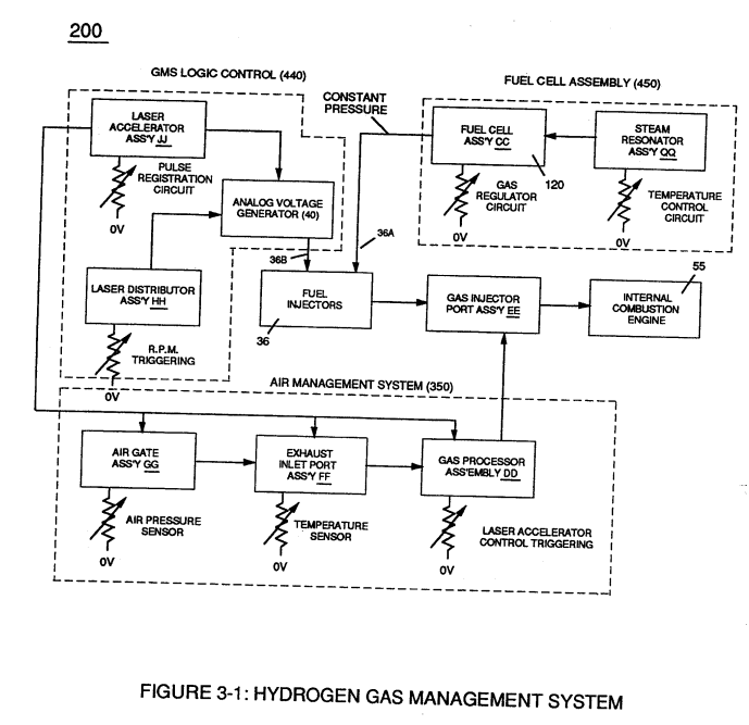
Second regulator stage (28) simply acts and function as a gas regulator (33) by preventing Fuel Gas production beyond a predetermined gas pressure level (34) of Figure (3-15) during Fuel Cell operations and, as such, maintains constant gas pressure to Fuel Injectors (36) of Figure (3-1) regardless of engine performance (R.P.M. response).
How it is written
- (36) 8×
- (33 / 36) 2× with (33) Applied Voltage Intensity
- (33/36) 2× with (33) Applied Voltage Intensity
- (33 /36) 1× with (33) Applied Voltage Intensity
Drawings 48
-
Figure (3-5) · Acceleration Control Circuit (30)
-
Analog Voltage Circuit (40), as shown in Figure (3-5) · Acceleration Control Circuit (30)
-
Figure (3-5) · Acceleration Control Circuit (30)
-
Figure (3-5) · Analog Voltage generator (40)
-
Figure (3-23) · Voltage Intensifier Circuit (60)
-
"Gas Modulator Process" (320) of Figure (3-36) · Gas Modulator Process
-
(330) of Figure (3-37) · Gas Modulator Process
-
(240) of Figure (3-31) · Gas Processor
-
Figure (3-5) · Laser Distributor
-
Carries this number · WFC 422DA - Illustrations
-
Carries this number · WFC 422DA - Illustrations
-
Carries this number · WFC 422DA - Illustrations
-
Carries this number · Differential Air-Gas Inlet Control
-
(70) of Figure (3B) · Water Fuel Injector (Taper Resonant Cavity Chamber)
-
Figure (3-31) · Water Fuel Injection System - Page 1
-
Activation Process (590) of Figure (6-2) · Voltage Intensifier Coil-Assembly
-
The figure it sits on · Laser Accelerator Assembly
-
Figure (3-1) · Voltage Amplitude Control Circuit (50)
-
To further prevent voltage fluctuation during resonant action, Phase Lock Loop technique of Pulse Indicator circuit (110) is utilized during pulsing operations. · Resonant Action
-
In terms of assembly, gas resonant cavity (410), electron extraction circuit (270), optical lens (121) forms gas processor (260) of Figure (3-31). · Gas Processor
-
In terms of assembly, gas resonant cavity (410), electron extraction circuit (270), optical lens (121) forms gas processor (260) of Figure (3-31). · Gas Processor
-
Figure (3-1) · Laser Distributor
-
Figure (3-2) · Laser Distributor
-
Hydrogen Fuel-Gas Assembly (450) of Figure (3-1) · Operational Parameters
-
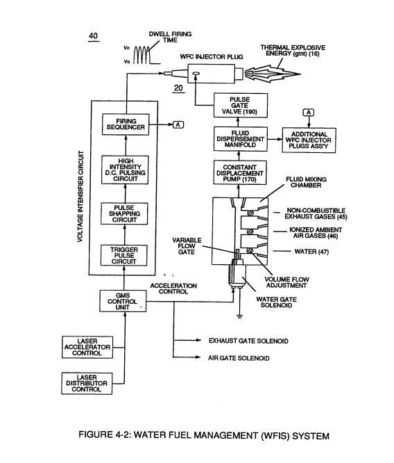
Water Fuel Injector Plug (40) of Figure (4-2) · Operational Parameters
-
The figure it sits on · WFC 422DA - Illustrations
-
The figure it sits on · WFC 422DA - Illustrations
-
3-2 (VIC) Coil Assembly · Voltage Intensifier Coil Assembly
-
The figure it sits on · Electronic Circuit Design
-
(220) of Figure (18) · Water Fuel Injector (Taper Resonant Cavity Chamber)
-
The figure it sits on · Water Fuel Injector (Taper Resonant Cavity Chamber)
-
The Following Page 1-7 was not available · Water Fuel Injector (Taper Resonant Cavity Chamber)
-
Figure (4-5) · Water Fuel Injection System - Page 1
-
Figure (4-2) · Water Fuel Injection System - Page 1
-
but, also prevents electron flow into destabilizing gas process (180), as so illustrated in Figure (4-5). · Water Fuel Injection System - Page 3
-
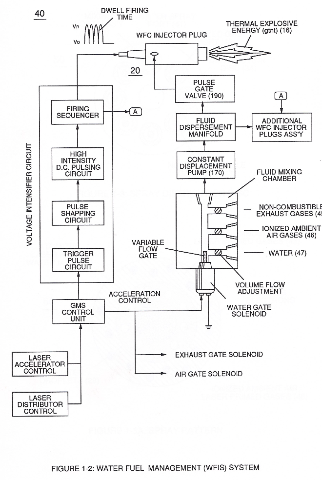
which simply uses Water Fuel Management (WFMS) System fluid-metering system (40) to control gas ignition (16), as illustrated in (40) of Figure (4-2). · Water Fuel Injection System - Page 4
-
The figure it sits on · In Application of Usage
-
Voltage Triggering Process (70) of Figure (4-5) · Voltage Intensifier Coil-Assembly
-
(16) of Figure (4-5) · Resistance (Rs)
-
Figure (4-5) · Capacitance Reactance
-
Figure (4-5) · 8-5 - Energy Vectoring (Ev)
-
(40) of Figure (4-2) · 8-5 - Energy Vectoring (Ev)
-
The figure it sits on · WFC 427 Illustrations
-
Figure (10-3 A/B) · Propagating Electrical Stress
-
The figure it sits on · WFC 429 - Illustrations
-
The figure it sits on · WFC 429 - Illustrations
-
The figure it sits on · WFC 429 - Illustrations
-
The figure it sits on · Wobbling Effect
Where it is named · 13
Voltage Amplitude Control Circuit (50) 3×
-
Fuel Injectors (36)
Second regulator stage (28) simply acts and function as a gas regulator (33) by preventing Fuel Gas production beyond a predetermined gas pressure level (34) of Figure (3-15) during Fuel Cell operations and, as such, maintains constant gas pressure to Fuel Injectors (36) of Figure (3-1) regardless of engine performance (R.P.M. response).
-
injection (36)
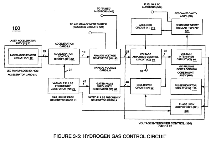
Conversely, analog signal (32) is always allowed to exceed voltage level (35) during injection (36) of Figure (3-1) until gas-point (34) is reached.
-
gas injector (36)
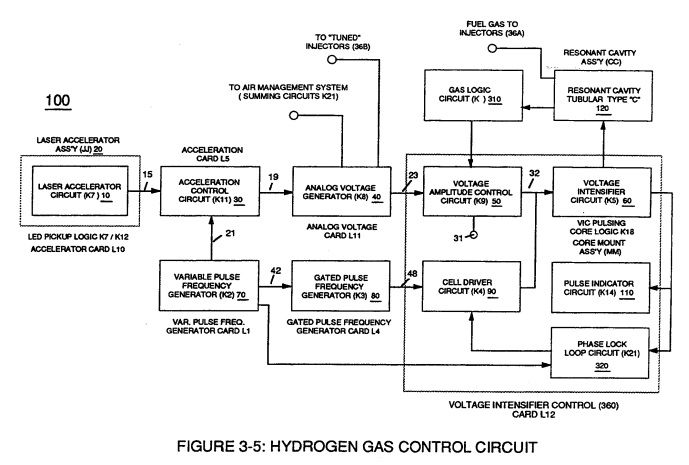
Gas logic circuit (310) of Figure (3-5) supplies logic function to Voltage amplitude control circuit (50) to maintain proper gas pressure to gas injector (36) of Figure (3-1) by electronically monitoring achieved gas pressure via pressure sensor (73) of Figure (3-24).
Resonant Action 1×
-
Fuel Injectors (36)
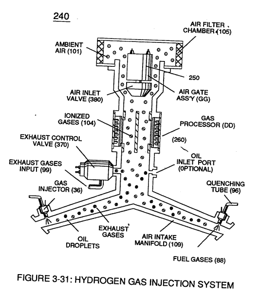
The resultant fuel-gas (88) is, now, transferred through Quenching Tube (96) of Figure (3-41) to, through and beyond Fuel Injectors (36) of Figure (3-1) for Hydrogen gas utilization.
Gas Processor 1×
-
injector port (36)
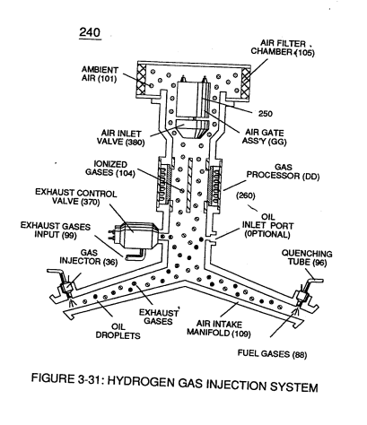
… ant and newly formed sub-critical gas atoms (104a xxx 104n) are directed onward through air intake manifold (109) of Figure (3-31) to and beyond both exhaust gas metering port (370) and injector port (36) where metered fuel-gas (88), metered exhaust gases (99), and metered sub-critical gas atoms (104a xxx 104n) forms gas-mixture (103) entering engine cylinder (102), as illustrated in (240) of Figure ( …
Laser Distributor 3×
-
Fuel-Injectors (36)
Interlocking Laser Accelerator output {JJ) with Laser Distributor output (HH) of Figure (3-1) causes Fuel-Injectors (36) to be "Tuned" with both Air Management System (350) of Figure (3-2) and Hydrogen Gas Control Circuit (100) of Figure (3-5) to maintain constant Fuel-mixing Ratio (290) of Figure (3-3) during engine performance.
-
Fuel-Injectors (36)
As Laser Accelerator (JJ) advances toward "Peak" engine performance, Fuel-Injectors (36) open gate-time (on-time) increases proportionally.
-
Injectors (36)
Opposite or reverse movement of Laser Accelerator (JI) decreases Injectors (36) on-time which, in turns, reduces engine speed.
Water Fuel Injection System 2×
-
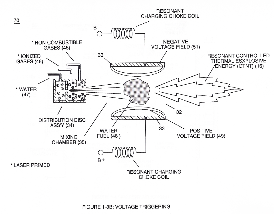
thirdly, the resultant moving Water-Fuel mixture (48) of Figure (3B) enters into Voltage Igniter Stage (180) of Figure (3B) and exposed to high intensity voltage fields (33 / 36) (typically 2,000 volts or above @ 10 Khz or above) opposite electrical polarity (E7 / E8)
-
Energy-Flame temperature is regulated by controlling the volume flow-rate of each fluid mediums (47 / 45/ 46) in direct relationship to applied voltage intensity (33 /36), as further stated in Figure (2B) as to Figure (3B).
Water Fuel Injector (Taper Resonant Cavity Chamber) 1×
-
Pulsing Transformer (33/36)
... forming a capacitor (E7 / E8) in series with Resonant Charging Chokes (56/57) placed on opposite sides of Resonant Cavity Zone (35) as to Figure (7) and (8) . . . forming a Resonant Pulsing Circuit (110) of Figure (7) with step-up Pulsing Transformer (33/36), as shown in (220) of Figure (18).
Water Fuel Injection System - Page 1 1×
-
thirdly, the resultant moving Water-Fuel mixture (48) of Figure (4-5) enters into Voltage Igniter Stage (180) of Figure (4-5) and exposed to high intensity voltage fields (33/36) (typically 2,000 volts or above @ 10 Khz or above) of opposite electrical polarity (E7 / E8)
Water Fuel Injection System - Page 2 1×
-
applied voltage intensity (33 / 36)
Energy-Flame temperature is regulated by controlling the volume flow-rate of each fluid-mediums (47 / 45 / 46) in direct relationship to applied voltage intensity (33 / 36), as further illustrated in Figure (4-2) as to Figure (4-5).