(180)
Voltage Igniter Stage
Also written Resonant Cavity · Taper Resonant Cavity · Taper Resonant Cavity Chamber · Resonant Cavity Chamber · inductor-capacitor circuit · gas ignition process
Where it is first named
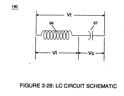
Resonant charging choke (56) in series with Excitor-Array (160) of Figure (25) forms an inductor-capacitor circuit (180) of Figure (3-28) since Excitor-Array (66/67) acts and performs as a capacitor (dielectric liquid between opposite electrical plates) during pulsing operations.
How it is written
- (180) 21×
Drawings 44
-
Figure (3-28) · Voltage Intensifier Circuit (60)
-
Ohm's law of LC circuit (180) of Figure (3-28) in series is given by (Eq 5) · Voltage Intensifier Circuit (60)
-
Carries this number · WFC 422DA - Illustrations
-
Carries this number · Water Fuel Injection System
-
Carries this number · Differential Air-Gas Inlet Control
-
Carries this number · Differential Air-Gas Inlet Control
-
Water Fuel Injection System (10) of Figure (1) · Water Fuel Injector (Taper Resonant Cavity Chamber)
-
Electronic Circuit (110) of Figure (7) · Water Fuel Injector (Taper Resonant Cavity Chamber)
-
Carries this number · Water Fuel Injector (Taper Resonant Cavity Chamber)
-
Carries this number · Funneling Effect
-
2-3 Water Inlet Housing · Water Fuel Injector Illustrations
-
Figure (4-8) · Water Fuel Injection System - Page 2
-
Figure (4-10) · Water Fuel Injection System - Page 2
-
Figure (4-9) · Water Fuel Injection System - Page 2
-
Figure (4-7) · Water Fuel Injection System - Page 3
-
but, also prevents electron flow into destabilizing gas process (180), as so illustrated in Figure (4-5). · Water Fuel Injection System - Page 3
-
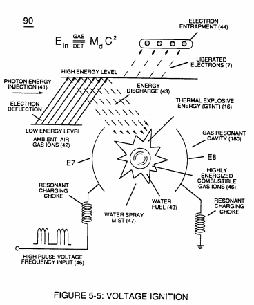
Figure (5-5) · Resonant Propagation
-
...converts water mist (68) into it's component gases hydrogen (77 a/b) oxygen (76) and ambient air gases (97); · Triggering Process
-
Figure (5-6) · Energy Recycling Spectrum
-
(100) of Figure (4-8) · In Application of Usage
-
(110) of Figure (4-9) · In Application of Usage
-
Carries this number · Illustrations
-
(100) of Figure (4-8) · Voltage Intensifier Coil-Assembly
-
(VIC) coil-assembly (530) of Figure (5-6) · Tri - Coil Construction
-
(110) of Figure (4-9) · Resistance (Rs)
-
(532) of Figure (5-6) · Capacitance (Cd)
-
(100) of Figure (4-8) · Capacitance Reactance
-
(90) of Figure (4-7) · Capacitance Reactance
-
... causing "electron clustering" (641a xxx 641n) to take place within Copper Wire Zone (52) during pulse on- time (T1) · Electron Bounce Phenomenon
-
(90) of Figure (5-5) · 8-2 - Traveling Voltage Wave-Guides
-
Resonant Cavity (90) of Figure (4-7) · 8-5 - Energy Vectoring (Ev)
-
Voltage Intensifier Circuit (110) of Figure (4-9) · WFC Exhaust Air Reclaimer
-
Blocking Diode (52) of Figure (4-9) · Propagating Electrical Stress
-
Voltage (Vc) of Figure (3-28) across the capacitor is given by (Eq 7) · Voltage Intensifier Circuit (60)
-
The figure it sits on · Electronic Circuit Design
-
The figure it sits on · Electronic Circuit Design
-
Figure (4-5) · Water Fuel Injection System - Page 1
-
The figure it sits on · In Application of Usage
-
Voltage Triggering Process (70) of Figure (4-5) · Voltage Intensifier Coil-Assembly
-
(16) of Figure (4-5) · Resistance (Rs)
-
(90) of Figure (5-5) · Capacitance Reactance
-
Figure (4-5) · Capacitance Reactance
-
Figure (4-5) · 8-5 - Energy Vectoring (Ev)
-
The figure it sits on · WFC 427 Illustrations
Where it is named · 21
Voltage Intensifier Circuit (60) 3×
-
inductor-capacitor circuit (180)
Resonant charging choke (56) in series with Excitor-Array (160) of Figure (25) forms an inductor-capacitor circuit (180) of Figure (3-28) since Excitor-Array (66/67) acts and performs as a capacitor (dielectric liquid between opposite electrical plates) during pulsing operations.
-
Inductor (56) and capacitor (57) properties of LC circuit (180) is therefore "tuned" to resonate at a given frequency.
-
Ohm's law of LC circuit (180) of Figure (3-28) in series is given by (Eq 5)

Water Fuel Injection System 5×
-
Voltage Igniter Stage (180)
thirdly, the resultant moving Water-Fuel mixture (48) of Figure (3B) enters into Voltage Igniter Stage (180) of Figure (3B) and exposed to high intensity voltage fields (33 / 36) (typically 2,000 volts or above @ 10 Khz or above) opposite electrical polarity (E7 / E8)
-
Voltage Igniter Stage (180)
Voltage Igniter Stage (180) of Figure (3B) as to Voltage Intensifier Circuit (110) Figure (7) as to Extraction Circuit (120) of Figure (8) performs several functions simultaneously to initiate and trigger thermal explosive energy-yield (gtnt) (16) beyond normal gas burning levels:
-
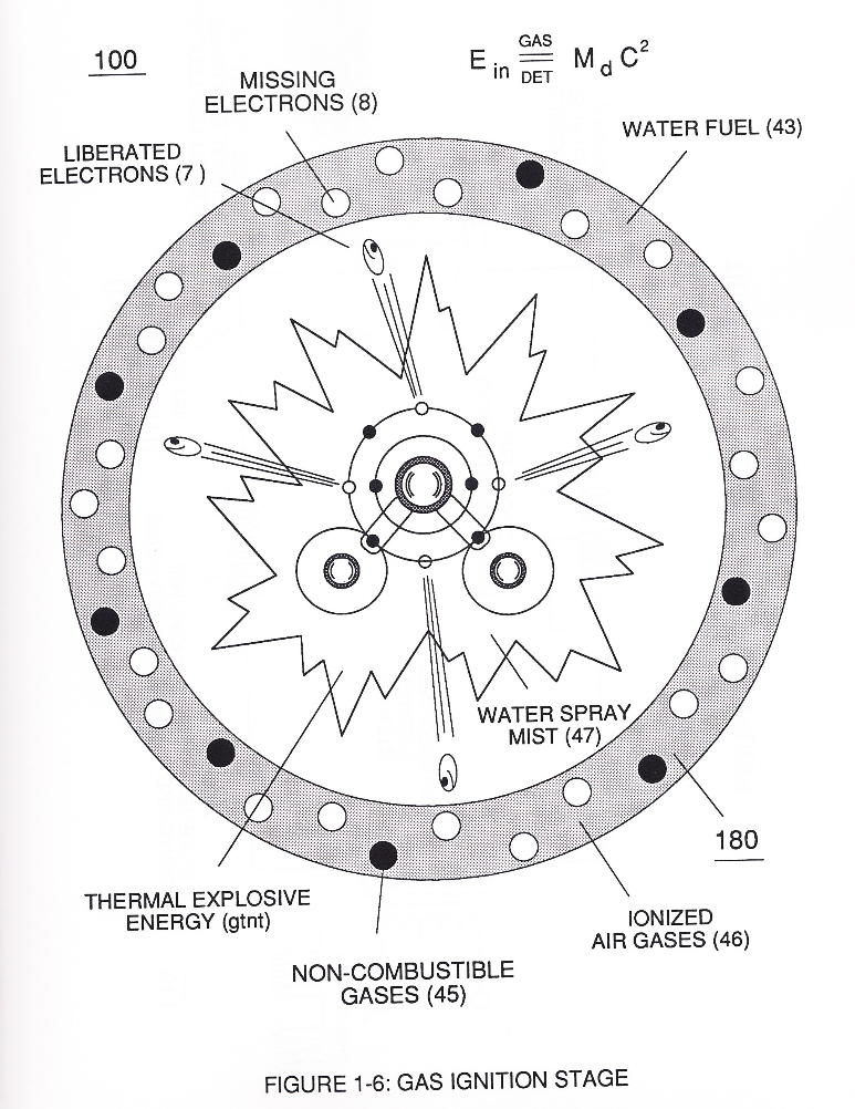
… experience electron ejection (230) of Figure (29) as to (71) of Figure (8) since voltage intensifier circuit (110) of Figure (7) inhibits and prevents electron flow to enter into gas ignition process (180), as further illustrated in Figure (6).
-
Incoming ambient air gases (5a xxx 5n) become laser primed and ionized when passing through Ambient Air Ionizer (Gas Processor) (80) of Figure (4) as to (10) of Figure (1) since electron extraction circuit (120) of Figure (8) not only captures and consumes ejected electrons (7a cx 7n) of Figure (6); but, also prevents electron flow into destabilizing gas process (180), as so illustrated in Figure (3B).
-
Voltage Igniter Stage (180)
In terms of performance reliability and safety, ionized air gases (46a xxx 46n) and liquid water (47a xxx 47n) do not become energy activated (volatile) until water-fuel mixture (48) reaches Voltage Igniter Stage (180).
Water Fuel Injector (Taper Resonant Cavity Chamber) 6×
-
Taper Resonant Cavity Chamber (180)
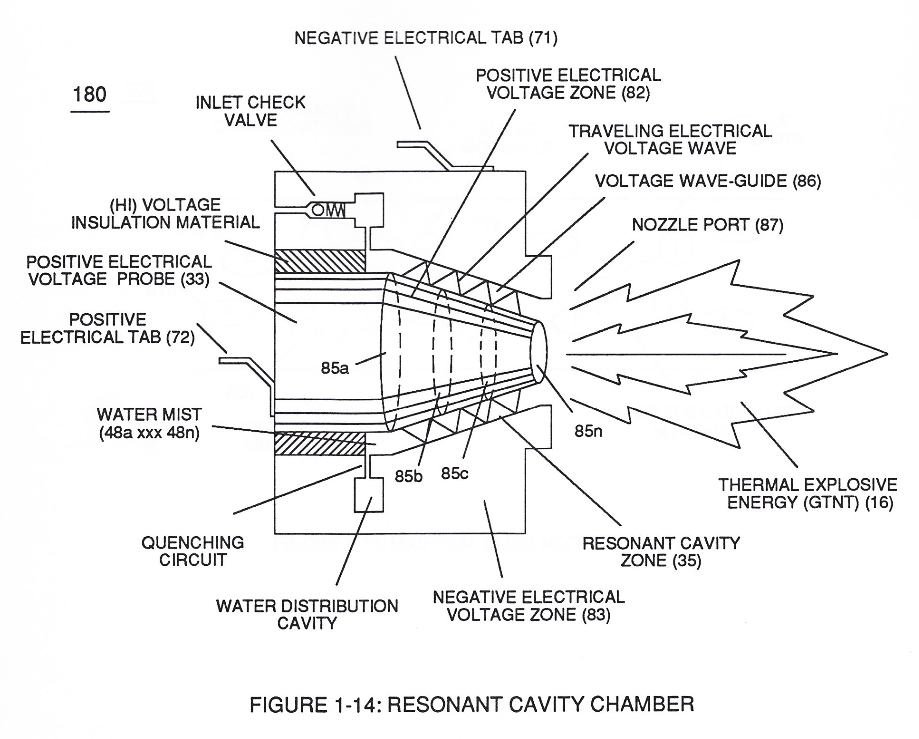
… energy (gtnt) via flame projection (16) of Figure (3B) as to Figure (14), Water Fuel Injection System (10) of Figure (1) as to (170) of Figure (13) incorporates and uses Taper Resonant Cavity Chamber (180) of Figure (14) to enhance operational parameters of Hydrogen Fracturing Process (100) of Figure (6) being stimulated to activation by opposite electrical voltage fields (49/51) of Figure (3B) as to ( …
-
… ) of Figure (14) to enhance operational parameters of Hydrogen Fracturing Process (100) of Figure (6) being stimulated to activation by opposite electrical voltage fields (49/51) of Figure (3B) as to (180) of Figure (14).
-
Taper Resonant Cavity (180)
The injected water fuel-droplets (48a xxx 48n), now, surrounds outer surface area of exposed positive probe (33) while entering into Taper Resonant Cavity (180), as illustrated in (70) of Figure (3B) as to Figure (14).
-
which, in turns, ejects a greater number of electrons while preventing the formation of the water molecule (390) of Figure (41) (WFC Memo 422 DA) during thermal gas-ignition (180) of Figure (14).
-
(180) of Figure (14)
-
Resonant Cavity (180)
This induced voltage phenomenon encourages and therefore prevents resonant pulse frequency (58) from being impaired or altered while being electrically transmitted to Resonant Cavity (180) of Figure (14) via electrical tabs (71) and (72) of Figure (14).
Funneling Effect 1×
-
Resonant Cavity Chamber (180)
At termination point (85), voltage intensity (VL x Va x Vb x Vc x Vn) is, now, increased to the point to cause Gas Ignition as Combustible Gas Atoms (76, 77a - 77b) which are, then, expelled from Gas Nozzle Port (87) of Figure (14) under dynamic pressure to allow thermal gas expansion (16) ... releasing thermal explosive energy (gtnt) beyond and away from Resonant Cavity Chamber (180), as illustrated in Figure (14).
Water Fuel Injection System - Page 1 1×
-
Voltage Igniter Stage (180)
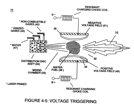
thirdly, the resultant moving Water-Fuel mixture (48) of Figure (4-5) enters into Voltage Igniter Stage (180) of Figure (4-5) and exposed to high intensity voltage fields (33/36) (typically 2,000 volts or above @ 10 Khz or above) of opposite electrical polarity (E7 / E8)
Water Fuel Injection System - Page 2 2×
-
Voltage Igniter Stage (180)
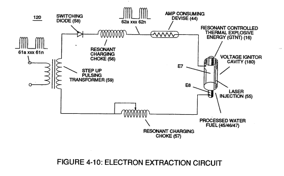
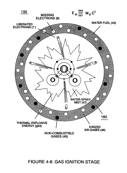
Voltage Igniter Stage (180) of Figure (4-5) as to Voltage Intensifier Circuit (110) Figure (4-9) as to Extraction Circuit (10) of Figure (4-10) performs several functions simultaneously to initiate and trigger thermal explosive energy-yield (gtnt) (16) beyond normal gas burning levels:
-
gas ignition process (180)
... which not only separates and splits the unlike atoms of the water molecule but also causes the unlike atoms (hydrogen atoms 77a /77b and oxygen atom 76) to experience electron ejection (230) of Figure (3-30) as to (71) of Figure (4-10) since voltage intensifier circuit (110) of Figure (4-9) inhibits and prevents electron flow to enter into gas ignition process (180), as further illustrated in Figure (4-8).
Water Fuel Injection System - Page 3 2×
-
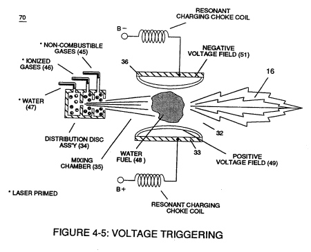
but, also prevents electron flow into destabilizing gas process (180), as so illustrated in Figure (4-5).
-
voltage Igniter Stage (180)
In terms of performance reliability and safety, ionized air gases (46a xxx 46n) and liquid water (47a xxx 47n) do not become energy activated (volatile) until water-fuel mixture (48) reaches voltage Igniter Stage (180).
Triggering Process 1×
-
Resonant Cavity (180)
As water mist (68a xxx 68n) is injected and metered into Resonant Cavity (180) of Figure (5-5) (Water Fuel Injector) under pressure, applied Resonant Pulse Voltage (46) performs several functions sequentially in a instant of time: