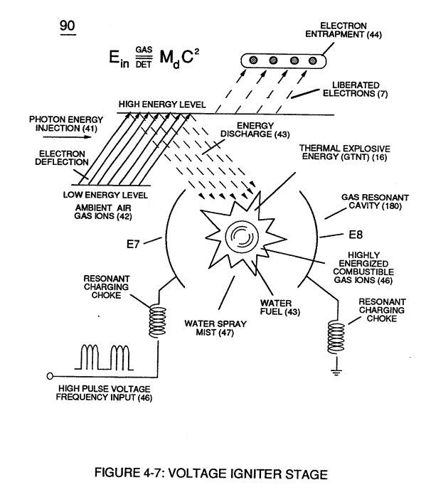
(46) · also written as a run, 46a xxx 46n
Ionized Ambient Air Gases
Also written ambient air gases · ionized air gases · fluid-displacement · ambient air ionized gases · ionized gases · pulse voltage frequency · Resonant Pulse Voltage · gated pulse train and 5 more
Where it is first named
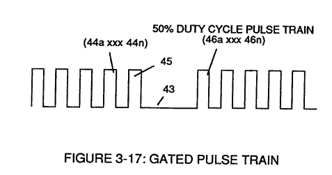
Gated Pulse Circuit (80) of Figure (3-5) switches "off' and "on" sections of incoming clock signal (42) to form gated pulse (45) which is, in turn, duplicated in succession to produce gated pulse train (46a xxx 46n) of Figure (3-17).
How it is written
- (46a xxx 46n) 10×
- (46) 8×
- (45 / 46 / 47) 3× with (45) Non-Combustible Gases, (47) Water Mist
- (46/47) 2× with (47) Water Mist
- (47 / 45/ 46) 1× with (47) Water Mist, (45) Non-Combustible Gases
- (400 xxx 46n) 1×
- (47/45/46) 1× with (47) Water Mist, (45) Non-Combustible Gases
- (45 / 46/ 47) 1× with (45) Non-Combustible Gases, (47) Water Mist
46a xxx 46n is Meyer's shorthand for a run of the same thing: 46a is the first, 46n the last, and the x's stand for however many lie between. Every stage of the run is this one numeral.
Drawings 73
-
Carries this number · Gated Pulse Frequency generator (80)
-
Figure (3-46) · Steam Resonator
-
Water Fuel Injector Plug (40) of Figure (4-2) · Operational Parameters
-
Carries this number · WFC 422DA - Illustrations
-
Carries this number · WFC 422DA - Illustrations
-
Carries this number · WFC 422DA - Illustrations
-
Carries this number · Water Fuel Injection System
-
Carries this number · Water Fuel Injection System
-
Carries this number · Electronic Circuit Design
-
Carries this number · Electronic Circuit Design
-
(170) of Figure (13) · Water Fuel Injector (Taper Resonant Cavity Chamber)
-
(170) of Figure (13) · Water Fuel Injector (Taper Resonant Cavity Chamber)
-
...positive charged gas particles (81a xxx 81n) being directed to and attached to negative charged oxygen atom (76) of water molecule (47); · Water Fuel Injector (Taper Resonant Cavity Chamber)
-
Fluid Displacement Pump (170) of Figure (13) · Water Fuel Injector (Taper Resonant Cavity Chamber)
-
(70) of Figure (3B) · Water Fuel Injector (Taper Resonant Cavity Chamber)
-
(80) of Figure (4) · Water Fuel Injector (Taper Resonant Cavity Chamber)
-
Electronic Circuit (110) of Figure (7) · Water Fuel Injector (Taper Resonant Cavity Chamber)
-
Figure (17) · Water Fuel Injector (Taper Resonant Cavity Chamber)
-
Carries this number · Funneling Effect
-
Carries this number · Funneling Effect
-
Figure (4-4) · Water Fuel Injection System - Page 1
-
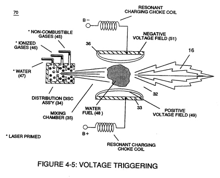
Figure (4-5) · Water Fuel Injection System - Page 1
-
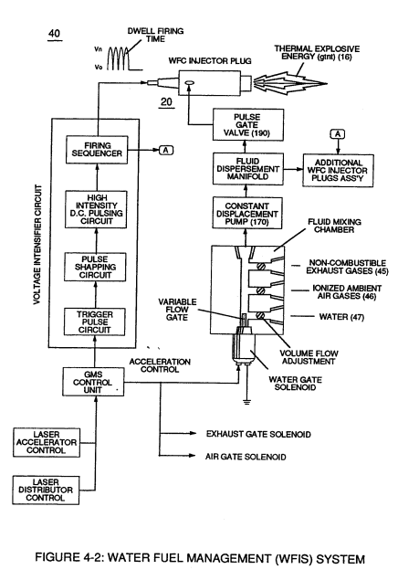
Figure (4-2) · Water Fuel Injection System - Page 1
-
Figure (4-8) · Water Fuel Injection System - Page 2
-
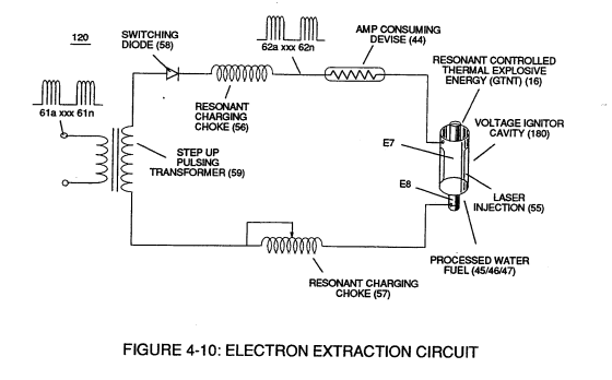
Figure (4-10) · Water Fuel Injection System - Page 2
-
Figure (4-9) · Water Fuel Injection System - Page 2
-
Figure (4-7) · Water Fuel Injection System - Page 3
-
Ambient Air Ionizer (Gas Processor) (80) of Figure (4-6) · Water Fuel Injection System - Page 3
-
but, also prevents electron flow into destabilizing gas process (180), as so illustrated in Figure (4-5). · Water Fuel Injection System - Page 3
-
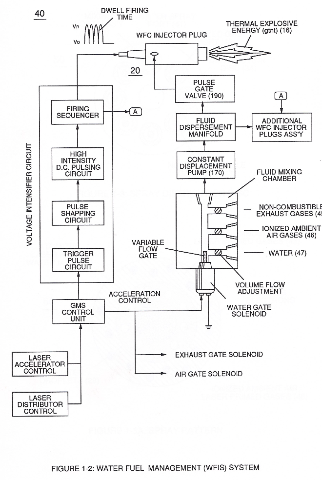
which simply uses Water Fuel Management (WFMS) System fluid-metering system (40) to control gas ignition (16), as illustrated in (40) of Figure (4-2). · Water Fuel Injection System - Page 4
-
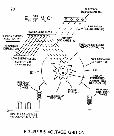
Figure (5-5) · Resonant Propagation
-
...converts water mist (68) into it's component gases hydrogen (77 a/b) oxygen (76) and ambient air gases (97); · Triggering Process
-
Figure (5-6) · Energy Recycling Spectrum
-
Carries this number · In Application of Usage
-
(100) of Figure (4-8) · In Application of Usage
-
(110) of Figure (4-9) · In Application of Usage
-
Carries this number · Illustrations
-
Voltage Triggering Process (70) of Figure (4-5) · Voltage Intensifier Coil-Assembly
-
coil-structures (580) of Figure (6-1) · Voltage Intensifier Coil-Assembly
-
(100) of Figure (4-8) · Voltage Intensifier Coil-Assembly
-
(VIC) coil-assembly (530) of Figure (5-6) · Tri - Coil Construction
-
(16) of Figure (4-5) · Resistance (Rs)
-
(110) of Figure (4-9) · Resistance (Rs)
-
(580) of Figure (6-1) · Inductance (FL)
-
(532) of Figure (5-6) · Capacitance (Cd)
-
(580) of Figure (6-1) · Multi-layer Coil
-
(100) of Figure (4-8) · Capacitance Reactance
-
(90) of Figure (5-5) · Capacitance Reactance
-
(90) of Figure (4-7) · Capacitance Reactance
-
Figure (4-5) · Capacitance Reactance
-
... causing "electron clustering" (641a xxx 641n) to take place within Copper Wire Zone (52) during pulse on- time (T1) · Electron Bounce Phenomenon
-
(580) of Figure (6-1) (WFC memo 425) · 8-2 - Traveling Voltage Wave-Guides
-
(90) of Figure (5-5) · 8-2 - Traveling Voltage Wave-Guides
-
Figure (4-5) · 8-5 - Energy Vectoring (Ev)
-
(40) of Figure (4-2) · 8-5 - Energy Vectoring (Ev)
-
Resonant Cavity (90) of Figure (4-7) · 8-5 - Energy Vectoring (Ev)
-
Voltage Intensifier Circuit (110) of Figure (4-9) · WFC Exhaust Air Reclaimer
-
Blocking Diode (52) of Figure (4-9) · Propagating Electrical Stress
-
(580) of Figure (6-1) · Voltage to Amp Differential Ratio
-
bipolar electrically charged water molecule (210) of Figure (3-46) · Voltage Flexing Process
-
The figure it sits on · Electronic Circuit Design
-
The figure it sits on · Electronic Circuit Design
-
The figure it sits on · Differential Air-Gas Inlet Control
-
(220) of Figure (18) · Water Fuel Injector (Taper Resonant Cavity Chamber)
-
The figure it sits on · Water Fuel Injector (Taper Resonant Cavity Chamber)
-
The Following Page 1-7 was not available · Water Fuel Injector (Taper Resonant Cavity Chamber)
-
thereby, attenuating voltage amplitude (voltage intensity) beyond Secondary Coil (53) voltage levels (71), as illustrated in (220) of Figure (18). · Funneling Effect
-
The figure it sits on · WFC 427 Illustrations
-
Figure (10-3 A/B) · Propagating Electrical Stress
-
The figure it sits on · WFC 429 - Illustrations
-
The figure it sits on · WFC 429 - Illustrations
-
The figure it sits on · WFC 429 - Illustrations
-
The figure it sits on · Wobbling Effect
Where it is named · 29
Gated Pulse Frequency generator (80) 1×
-
gated pulse train (46a xxx 46n)
Gated Pulse Circuit (80) of Figure (3-5) switches "off' and "on" sections of incoming clock signal (42) to form gated pulse (45) which is, in turn, duplicated in succession to produce gated pulse train (46a xxx 46n) of Figure (3-17).
Water Fuel Injection System 10×
-
ionized air gases (46a xxx 46n)
Secondly, ionized air gases (46a xxx 46n) of Figure (3A) (laser primed ambient air gases having missing electrons) produced by Ambient Air Ionizer (80) of Figure (4) as to Figure (1) and non-combustible gases (45) of Figure (3A) are intermixed with expelling water mist (47a xxx 47n) to form Water-fuel mixture (48) by way of gas mixing disc (34) of Figure (3B) as to (30) of Figure (2A);
-
ionized ambient air gases (46)
To ensure proper energy-flame projection and subsequent energy-flame stability, constant placement water pump (170) causes and allows ionized ambient air gases (46), non-combustible gases (45), and water (47) to be displaced under static pressure up to and beyond 125 psi respectively.
-
Energy-Flame density is enhanced and sustained by causing ionized gases (46a xxx 46n) of spray port (42) to be deflected into liquid spray path (41), together water mist (47) and ionized air (46) are, now, directed toward and deflected through non-combustible gas spray path producing uniformed water-fuel mixture (48), as illustrated in Figure (3B).
-
ionized air (46)
Energy-Flame density is enhanced and sustained by causing ionized gases (46a xxx 46n) of spray port (42) to be deflected into liquid spray path (41), together water mist (47) and ionized air (46) are, now, directed toward and deflected through non-combustible gas spray path producing uniformed water-fuel mixture (48), as illustrated in Figure (3B).
-
Energy-Flame temperature is regulated by controlling the volume flow-rate of each fluid mediums (47 / 45/ 46) in direct relationship to applied voltage intensity (33 /36), as further stated in Figure (2B) as to Figure (3B).
-
fluid-displacement (46/47)
To elevate Energy-flame-temperature still further, help increase fluid-displacement (46/47) while maintaining or reducing the volume flow rate of non-combustible gases (45) during an increase of applied voltage amplitude (Vo x Vn) of Figure (32) as to Voltage Intensifier Circuit (110) of Figure (7) and Electron Extraction Circuit (120) of Figure (8).
-
To lower Energy-flame temperature simply increase the amount of non-combustible gas (45a xxx) or reduced the fluid flow rate (45 / 46/ 47)) uniformly while lowering pulse voltage amplitude (xxx Vo).
-
To establish a predetermined or given Energy-flame temperature adjust fluid-medium (45 / 46 / 47)) and applied voltage amplitude (Vo xxx) independent of each other to obtain the desired results.
-
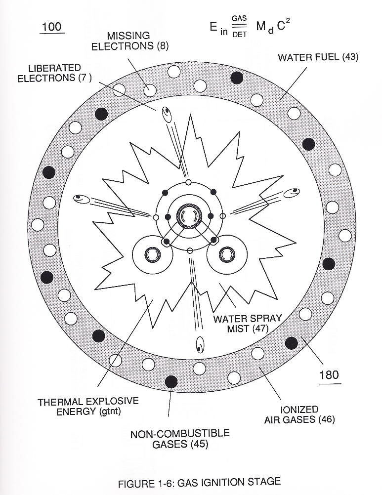
In terms of performance reliability and safety, ionized air gases (46a xxx 46n) and liquid water (47a xxx 47n) do not become energy activated (volatile) until water-fuel mixture (48) reaches Voltage Igniter Stage (180).
-
ambient air gases (46a xxx 46n)
especially when ionized ambient air gases (46a xxx 46n) and non-combustible gases (45a xxx 45n) are intermixed with water supply (47) prior to entering.
Water Fuel Injector (Taper Resonant Cavity Chamber) 2×
-
ambient air ionized gases (46)
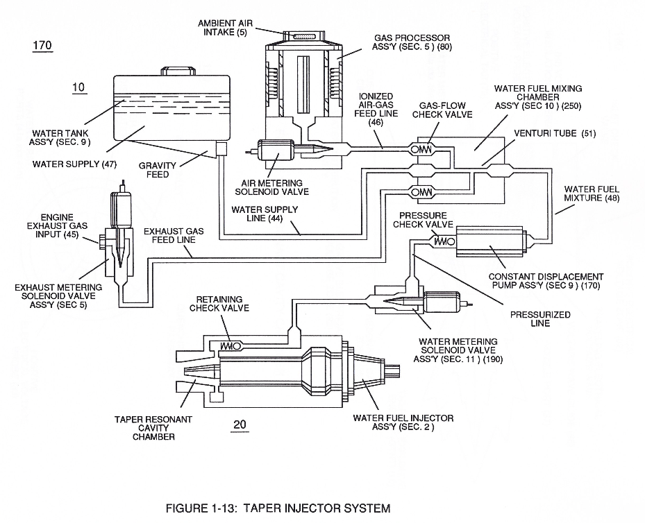
In like manner, water supply (10) of Figure (170), non-combustible gases (45) (Engine Exhaust gases), and ambient air ionized gases (46) (air gases having missing electrons) are uniformly intermixed when moving into, passing through and beyond fluid mixing chamber (250) of Figure (13) by way of venturi tube-cavity (51)...
-
allowing water fuel mixture (47/45/46) (48) to be particle aligned by opposite electrostatically charged atoms
Water Fuel Injection System - Page 1 1×
-
ionized air gases (46a xxx 46n)
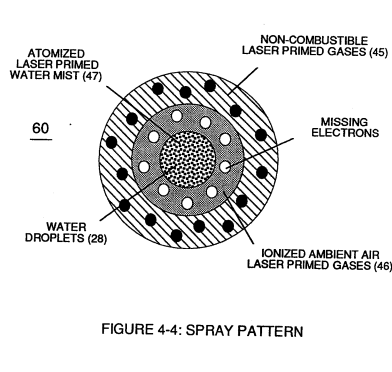
Secondly, ionized air gases (46a xxx 46n) of Figure (4-4) (laser primed ambient air gases having missing electrons) produced by Ambient Air Ionizer (80) of Figure (4-6) as to Figure (4-1) and non-combustible gases (45) of Figure (4-4) are intermixed with expelling water mist (47a xxx 47n) to form Water-fuel mixture (48) by way of gas mixing disc (34) of Figure (4-5) as to (30) of Figure (4-2);
Water Fuel Injection System - Page 2 7×
-
ionized ambient air gases (46)
To ensure proper energy-flame projection and subsequent energy-flame stability, constant displacement water pump (170) causes and allows ionized ambient air gases (46), noncombustible gases (45), and water (47) to be displaced under static pressure up to and beyond 125 lbs psi, respectively.
-
ionized gases (46a xxx 46n)
Energy-Flame density is enhanced and sustained by causing ionized gases (46a xxx 46n) of spray port (42) to be deflected into liquid spray path (41), together water mist (47) and ionized air gas (46) are, now, directed toward and deflected through non-combustible gas spray path (43)
-
ionized air gas (46)
Energy-Flame density is enhanced and sustained by causing ionized gases (46a xxx 46n) of spray port (42) to be deflected into liquid spray path (41), together water mist (47) and ionized air gas (46) are, now, directed toward and deflected through non-combustible gas spray path (43)
-
fluid-mediums (47 / 45 / 46)
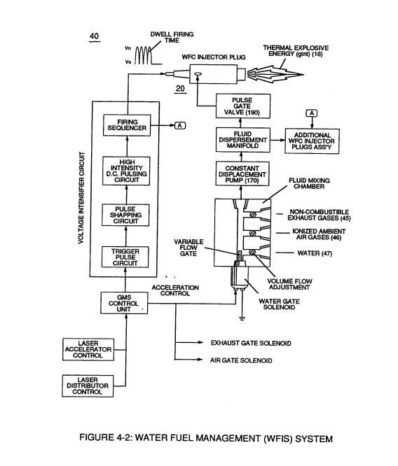
Energy-Flame temperature is regulated by controlling the volume flow-rate of each fluid-mediums (47 / 45 / 46) in direct relationship to applied voltage intensity (33 / 36), as further illustrated in Figure (4-2) as to Figure (4-5).
-
fluid-displacement (46/47)
To elevate Energy-flame-temperature still further, simply increase fluid-displacement (46/47) while maintaining or reducing the volume flow rate of non-combustible gases (45) during an increase of applied voltage amplitude (V0 xxx Vo) of Figure (4-2) as to Voltage Intensifier Circuit (110) of Figure (4-9) and Electron Extraction Circuit (120) of Figure (4-10).
-
fluid flow rate (45 / 46 / 47)
To lower Energy-flame temperature simply increase the amount of non-combustible gases (45a xxx) or reduced the fluid flow rate (45 / 46 / 47) uniformly while lowering pulse voltage amplitude (xxx V0).
-
fluid-medium (45 / 46 / 47)
To establish a predetermined or given Energy-flame temperature adjust fluid-medium (45 / 46 / 47) and applied voltage amplitude (V0 xxx) independent of each other to obtain the desired results.
Water Fuel Injection System - Page 3 1×
-
ionized air gases (46a xxx 46n)
In terms of performance reliability and safety, ionized air gases (46a xxx 46n) and liquid water (47a xxx 47n) do not become energy activated (volatile) until water-fuel mixture (48) reaches voltage Igniter Stage (180).
Water Fuel Injection System - Page 4 1×
-
ionized ambient air gases (400 xxx 46n)
... especially when ionized ambient air gases (400 xxx 46n) and non-combustible gases (45a xxx 45n) are intermixed with water supply (47) prior to entering Water Fuel Injector Plug (20/30), as illustrated in (40) of Figure (4-2) as to (10) of Figure (4-1).
Resonant Propagation 2×
-
pulse voltage frequency (46)
Resonant Action (21) (point of particle oscillation) occurs when applied pulse voltage frequency (46) of Figure (5-5) is adjusted to "tune-in" to the Dielectric Resonance of water via voltage Intensifier Circuit (60) of Figure (5 -3);
-
(46) of Figure (5-5)
Triggering Process 1×
-
Resonant Pulse Voltage (46)
As water mist (68a xxx 68n) is injected and metered into Resonant Cavity (180) of Figure (5-5) (Water Fuel Injector) under pressure, applied Resonant Pulse Voltage (46) performs several functions sequentially in a instant of time:
Water Fuel Injector 1×
-
As incoming gated pulse-train (46a xxx 46n) of Figure (3-17) is electronically "tuned" to adjust pulse off- time (T2) to compensate for "rise" and "fall" of magnetic field coupling (71a xxx 71n) for a predetermined resonant pulse-frequency established and determined by the dielectric value of natural water in direct relationship to resonant cavity geometrical configuration
Instant Explosion of Water 1×
-
... producing unipolar voltage wave-form (64a xxx 64n) during repeated pulse-signal (46a xxx 46n) on-time (T1a xxx T1n)
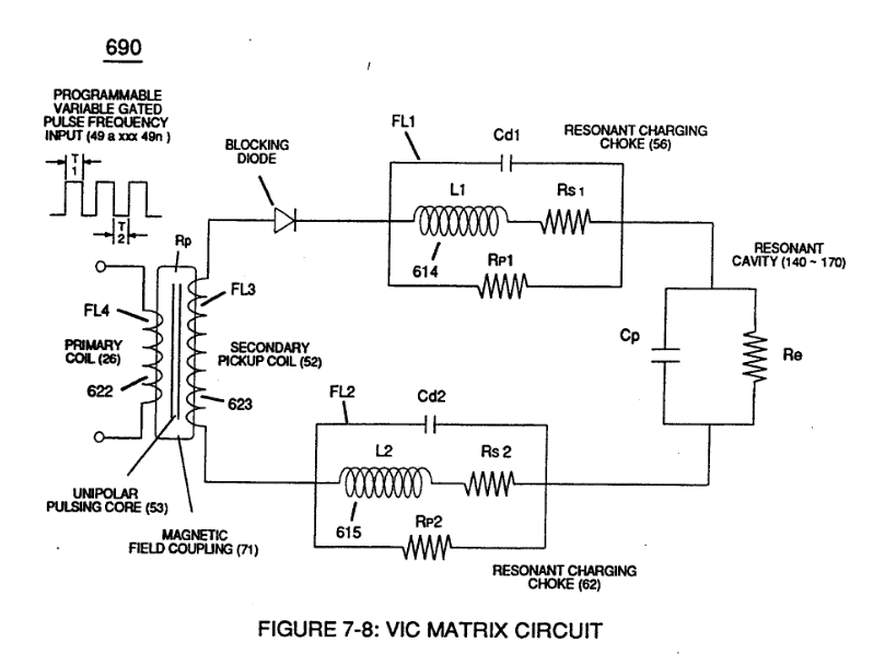
Capacitance Reactance 1×
-
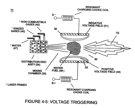
which, when occurring at gas exit port (32) of Figure (4-5), spark-ignites expanding water gas-fuel (45/46/47) of Figure (4-5) during water inject cycle (70) of Figure (4-5)