(34) · also written as a run, 34a xxx 34n
Gas Mixing Disc
Also written gas pressure · gas pressure level · gas point · gas-point
Where it is first named
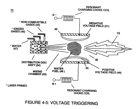
Second regulator stage (28) simply acts and function as a gas regulator (33) by preventing Fuel Gas production beyond a predetermined gas pressure level (34) of Figure (3-15) during Fuel Cell operations and, as such, maintains constant gas pressure to Fuel Injectors (36) of Figure (3-1) regardless of engine performance (R.P.M. response).
How it is written
- (34) 8×
- (34a xx) 1×
34a xxx 34n is Meyer's shorthand for a run of the same thing: 34a is the first, 34n the last, and the x's stand for however many lie between. Every stage of the run is this one numeral.
Drawings 39
-
Figure (3-15) · Voltage Amplitude Control Circuit (50)
-
(270) of Figure (3-34) · Gas Processor
-
Carries this number · WFC 422DA - Illustrations
-
Carries this number · WFC 422DA - Illustrations
-
Carries this number · Water Fuel Injection System
-
(70) of Figure (3B) · Water Fuel Injector (Taper Resonant Cavity Chamber)
-
(280) of Figure (34) · Funneling Effect
-
Figure (4-5) · Water Fuel Injection System - Page 1
-
but, also prevents electron flow into destabilizing gas process (180), as so illustrated in Figure (4-5). · Water Fuel Injection System - Page 3
-
Carries this number · In Application of Usage
-
(230) of Figure (3-30) · In Application of Usage
-
(270) of (3-34) · In Application of Usage
-
Voltage Triggering Process (70) of Figure (4-5) · Voltage Intensifier Coil-Assembly
-
(16) of Figure (4-5) · Resistance (Rs)
-
Figure (4-5) · Capacitance Reactance
-
Figure (4-5) · 8-5 - Energy Vectoring (Ev)
-
Figure (3-34) · Propagating Electrical Stress
-
blocking diode (55) of Figure (3-34) · Voltage to Amp Differential Ratio
-
The figure it sits on · Laser Accelerator Assembly
-
Figure (3-6) · Voltage Amplitude Control Circuit (50)
-
Figure (3-1) · Voltage Amplitude Control Circuit (50)
-
Figure (3-24) · Voltage Amplitude Control Circuit (50)
-
Figure (3-6) · Cell Driver Circuit (90)
-
Figure (3-24) · Electrical Polarization process
-
To further prevent voltage fluctuation during resonant action, Phase Lock Loop technique of Pulse Indicator circuit (110) is utilized during pulsing operations. · Resonant Action
-
Figure (3-1) · Laser Distributor
-
Hydrogen Fuel-Gas Assembly (450) of Figure (3-1) · Operational Parameters
-
Fuel Cell (120) of Figure (3-24) · Operational Parameters
-
The figure it sits on · WFC 422DA - Illustrations
-
The figure it sits on · WFC 422DA - Illustrations
-
The figure it sits on · WFC 422DA - Illustrations
-
3-6 Pulsing Core · Voltage Intensifier Coil Assembly
-
3-15 VIC Mount Plate · Voltage Intensifier Coil Assembly
-
The figure it sits on · Electronic Circuit Design
-
The figure it sits on · Electronic Circuit Design
-
(520) of Figure (4-3) · Funneling Effect
-
Figure (3-6) · Water Fuel Injection System - Page 1
-
Figure (3-24) · Inductance (FL)
-
The figure it sits on · WFC 427 Illustrations
Where it is named · 9
Voltage Amplitude Control Circuit (50) 5×
-
gas pressure level (34)
Second regulator stage (28) simply acts and function as a gas regulator (33) by preventing Fuel Gas production beyond a predetermined gas pressure level (34) of Figure (3-15) during Fuel Cell operations and, as such, maintains constant gas pressure to Fuel Injectors (36) of Figure (3-1) regardless of engine performance (R.P.M. response).
-
gas pressure (34)
If for example, Fuel Gas production is greater than demand, then, analog signal (32) is reduced to proper voltage level (35) (voltage level directly determines gas pressure via Resonant Action) required to maintain gas pressure (34).
-
gas-point (34)
Conversely, analog signal (32) is always allowed to exceed voltage level (35) during injection (36) of Figure (3-1) until gas-point (34) is reached.
-
gas pressure (34a xx)
If gas pressure (34a xx) should exceed gas point (35) during injector off-time, gas pressure release valve (75) of Figure (3-24) (gas venting 37 of Figure 3-15) expels Fuel gases (88) until gas point (34) is either reached o …
-
gas point (34)
If gas pressure (34a xx) should exceed gas point (35) during injector off-time, gas pressure release valve (75) of Figure (3-24) (gas venting 37 of Figure 3-15) expels Fuel gases (88) until gas point (34) is either reached or a delay timing circuit activates Safety Control Circuit (14) of Figure (3-6) which, in turns, switches off or disconnects applied electrical power (28) to Fuel Cell electrical sy …
Water Fuel Injection System 1×
-
gas mixing disc (34)
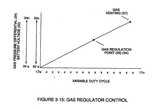
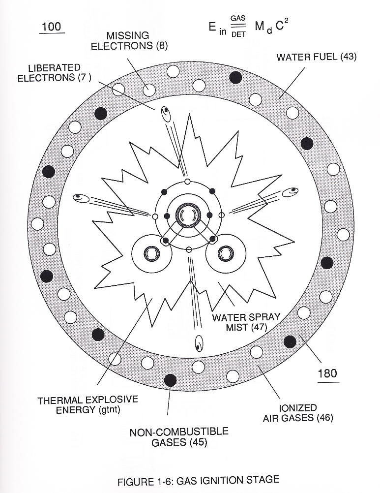
Secondly, ionized air gases (46a xxx 46n) of Figure (3A) (laser primed ambient air gases having missing electrons) produced by Ambient Air Ionizer (80) of Figure (4) as to Figure (1) and non-combustible gases (45) of Figure (3A) are intermixed with expelling water mist (47a xxx 47n) to form Water-fuel mixture (48) by way of gas mixing disc (34) of Figure (3B) as to (30) of Figure (2A);
Funneling Effect 2×
-
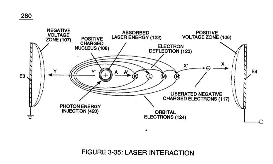
As voltage intensity increases (VL x Va x Vb) onward segmental point (85b), Energy Pumping Action (520) of Figure (4-3) (WFC Memo 424) as to (280) of Figure (34) (WFC Memo 422 DA) is activated to peak performance levels.
-
(280) of Figure (34)
Water Fuel Injection System - Page 1 1×
-
gas mixing disc (34)
Secondly, ionized air gases (46a xxx 46n) of Figure (4-4) (laser primed ambient air gases having missing electrons) produced by Ambient Air Ionizer (80) of Figure (4-6) as to Figure (4-1) and non-combustible gases (45) of Figure (4-4) are intermixed with expelling water mist (47a xxx 47n) to form Water-fuel mixture (48) by way of gas mixing disc (34) of Figure (4-5) as to (30) of Figure (4-2);