(29)
Battery Voltage Potential
Where it is first named
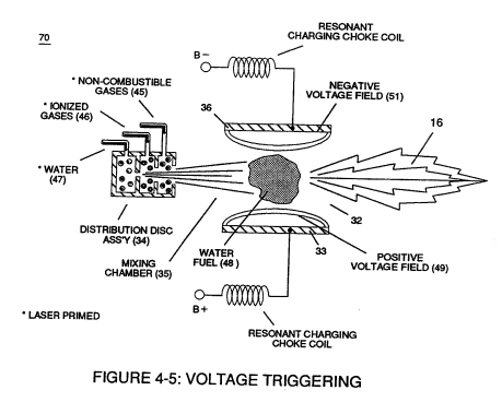
Regulator stage (27) of circuit (50) converts battery voltage potential (29) of Figure (3-6) via electrical terminal (31) of Figure (3-5) as to Figure (3-6) into a analog voltage signal (32) of Figure (3-15) which corresponds to but is electrically isolated (crossover voltage from two separate power supplies) from incoming gas volume signal (23) of Figure (3-14), as shown in Figure (35).
How it is written
- (29) 8×
Drawings 27
-
Carries this number · Magnetic Field Enhancement
-
In both cases, electrical charge deflection or movement is directly related to applied voltage (65). · Voltage Dynamics
-
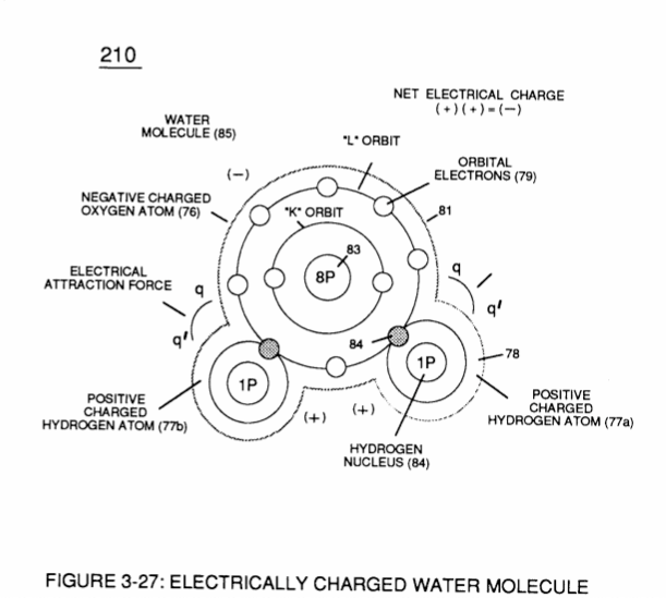
Figure (3-29) · Electrically Charged Water Molecule
-
Carries this number · WFC 422DA - Illustrations
-
Carries this number · Water Fuel Injection System
-
3-15 VIC Mount Plate · Voltage Intensifier Coil Assembly
-
Carries this number · Electronic Circuit Design
-
Electron Ejection Process (230) of Figure (29) · Water Fuel Injector (Taper Resonant Cavity Chamber)
-
Figure (29) · Water Fuel Injector (Taper Resonant Cavity Chamber)
-
Carries this number · Transformer Action
-
Carries this number · Electron Bounce Phenomenon
-
Voltage Dynamics (220) of Figure (3-29) · Electron Bounce Phenomenon
-
Voltage Dynamics (220) of Figure (3-29) · WFC Exhaust Air Reclaimer
-
Figure (3-6) · Voltage Amplitude Control Circuit (50)
-
Figure (3-6) · Cell Driver Circuit (90)
-
The figure it sits on · WFC 422DA - Illustrations
-
3-6 Pulsing Core · Voltage Intensifier Coil Assembly
-
The figure it sits on · Electronic Circuit Design
-
Figure (3-6) · Water Fuel Injection System - Page 1
-
Figure (4-5) · Water Fuel Injection System - Page 1
-
but, also prevents electron flow into destabilizing gas process (180), as so illustrated in Figure (4-5). · Water Fuel Injection System - Page 3
-
The figure it sits on · In Application of Usage
-
Voltage Triggering Process (70) of Figure (4-5) · Voltage Intensifier Coil-Assembly
-
(16) of Figure (4-5) · Resistance (Rs)
-
Figure (4-5) · Capacitance Reactance
-
Figure (4-5) · 8-5 - Energy Vectoring (Ev)
-
The figure it sits on · WFC 427 Illustrations
Where it is named · 8
Voltage Amplitude Control Circuit (50) 1×
-
battery voltage potential (29)
Regulator stage (27) of circuit (50) converts battery voltage potential (29) of Figure (3-6) via electrical terminal (31) of Figure (3-5) as to Figure (3-6) into a analog voltage signal (32) of Figure (3-15) which corresponds to but is electrically isolated (crossover voltage from two separate power supplies) from incoming gas volume signal (23) of Figure (3-14), as shown in Figure (35).
Water Fuel Injection System 2×
-
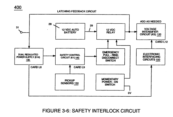
The resultant energy-flame pattern is further maintained by allowing the ignited,compressed, and moving gases (29) of Figure (3B) to be projected to, pass through and beyond nozzle-port (32) under pressure due to gas expansion caused by thermal gas ignition.
-
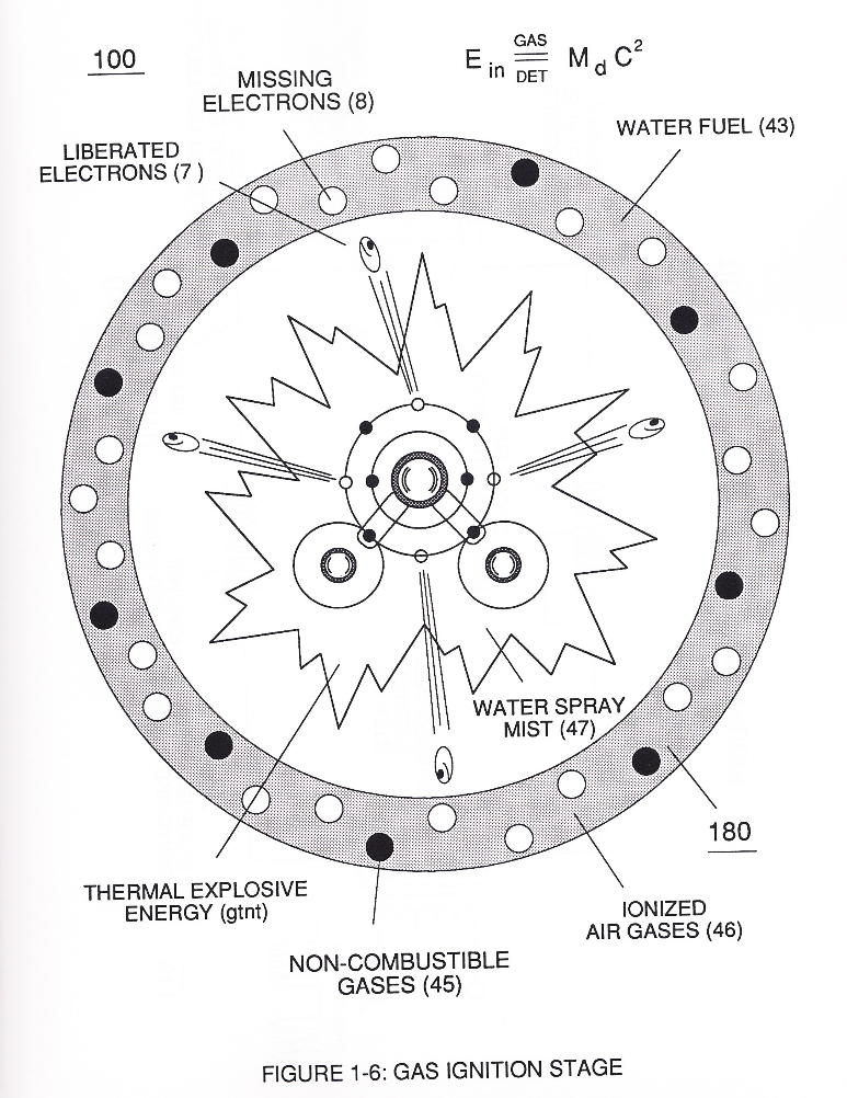
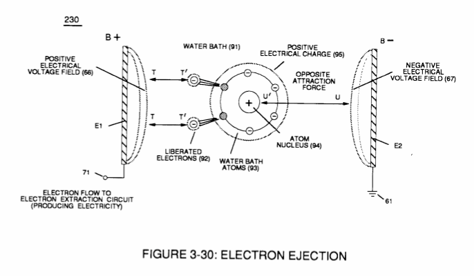
… ich not only separates and splits the unlike atoms of the water molecule but also causes the unlike atoms (hydrogen atoms 77a / 77b and oxygen atom 76) to experience electron ejection (230) of Figure (29) as to (71) of Figure (8) since voltage intensifier circuit (110) of Figure (7) inhibits and prevents electron flow to enter into gas ignition process (180), as further illustrated in Figure (6).
Water Fuel Injector (Taper Resonant Cavity Chamber) 4×
-
thirdly, by ionizing the released combustible gases by way of Electron Ejection Process (230) of Figure (29) (WFC Memo 422 DA), as further illustrated in (80) of Figure (4);
-
Electron Ejection Process (230) of Figure (29)
-
This further increase in voltage amplitude (xxxx VL) simply exerts a greater magnitude of opposite Electrical-Stress (SS'-RR') of Figure (25) (TT' - UU') of Figure (29) (WFC Memo 422 DA) across combustible gas atoms (76, 77a - 77b)
-
Figure (29)
Water Fuel Injection System - Page 2 1×
-
The resultant energy-flame pattern is further maintained by allowing the ignited, compressed, and moving gases (29) of Figure (4-5) to be projected to, pass through and beyond nozzle-port (32) under pressure due to gas expansion caused by thermal gas ignition.