(30)
Circuit
Also written Acceleration Control Circuit · accelerated control circuit · scanning circuit · Water Fuel Injector Plug · Water Fuel Injector
Where it is first named
This variable response-time (14axx ... 12 ... xxI4n) or signal output (15) of Figure (3-5) is, now, electrically transmitted to Acceleration Control Circuit (30) of Figure (3-5) since Laser Accelerator Assembly (20) of figure (3-10) converts mechanical displacement (9a xxx 9n) to electrical time-response (14a xxx 14n) of Figure (3-7) by linearly moving (forwa …
How it is written
- (30) 18×
- (20/30) 3× with (20) Laser Accelerator Assembly
- (20 / 30) 1× with (20) Laser Accelerator Assembly
Drawings 58
-
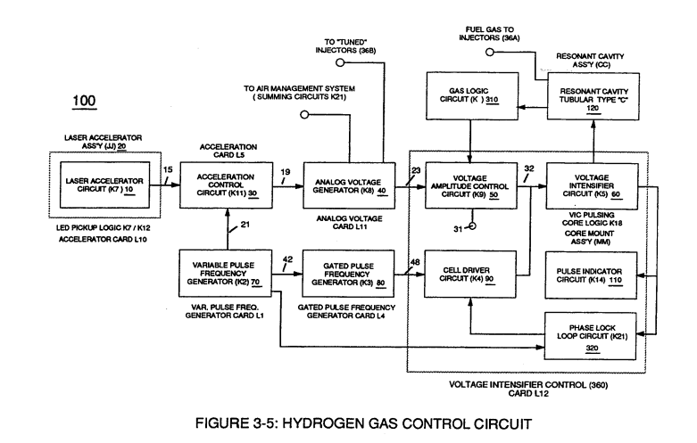
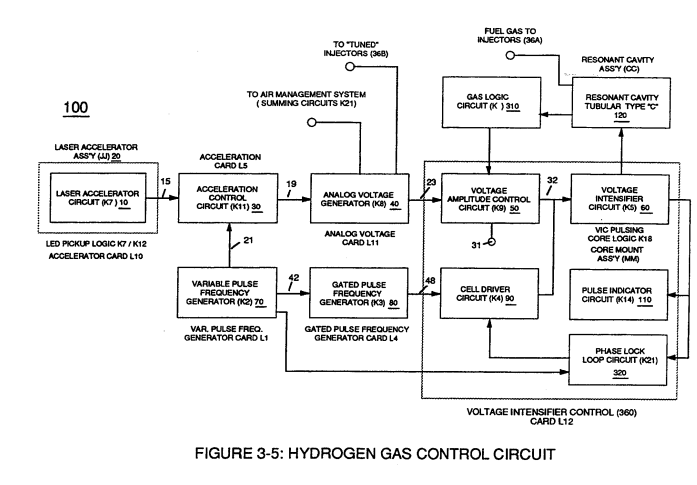
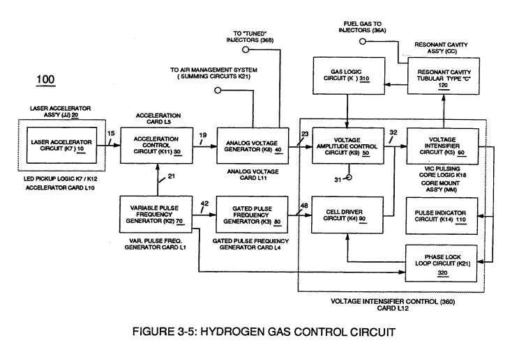
Figure (3-5) · Acceleration Control Circuit (30)
-
Analog Voltage Circuit (40), as shown in Figure (3-5) · Acceleration Control Circuit (30)
-
Figure (3-5) · Acceleration Control Circuit (30)
-
Figure (3-5) · Analog Voltage generator (40)
-
Figure (3-30) · Resonant Action
-
Figure (3-5) · Laser Distributor
-
Carries this number · WFC 422DA - Illustrations
-
Carries this number · WFC 422DA - Illustrations
-
Carries this number · WFC 422DA - Illustrations
-
3-4 Inner Core Bobbin · Voltage Intensifier Coil Assembly
-
Carries this number · Electronic Circuit Design
-
Carries this number · Electronic Circuit Design
-
Carries this number · Electronic Circuit Design
-
Electron Ejection Process (230) of Figure (29) · Water Fuel Injector (Taper Resonant Cavity Chamber)
-
Carries this number · Funneling Effect
-
2-3 Water Inlet Housing · Water Fuel Injector Illustrations
-
Carries this number · Steam Resonator Assembly
-
Carries this number · Cover Page
-
Figure (3-30) · Water Fuel Injection System - Page 2
-
(230) of Figure (3-30) · In Application of Usage
-
coil-structures (580) of Figure (6-1) · Voltage Intensifier Coil-Assembly
-
(630) of Figure (7-2) · Inductance (FL)
-
(580) of Figure (6-1) · Inductance (FL)
-
LC circuit of Figure (7-2) · Inductance (FL)
-
(580) of Figure (6-1) · Multi-layer Coil
-
(L1) and L2) are the inductances of each individual transformer coils (26)(52), · Transformer Action
-
Carries this number · Electron Bounce Phenomenon
-
(580) of Figure (6-1) (WFC memo 425) · 8-2 - Traveling Voltage Wave-Guides
-
(580) of Figure (6-1) · Voltage to Amp Differential Ratio
-
Led Pickup Circuit (10) of Figure (3-9) · Laser Accelerator Assembly
-
The figure it sits on · Acceleration Control Circuit (30)
-
Toggling action at full-scale deflection (13a xxx 13n) occurs in the range of (10) kHz or above and thus, allows instant response to driver's acceleration demands. · Acceleration Control Circuit (30)
-
Figure (3-13) · Acceleration Control Circuit (30)
-
Figure (3-13) · Acceleration Control Circuit (30)
-
reciprocating WFC Fuel-kits can be similar to Car design (340); · Aviation Application
-
Figure (4-11) · Aviation Application
-
Water Fuel Injector Plug (40) of Figure (4-2) · Operational Parameters
-
The figure it sits on · WFC 422DA - Illustrations
-
The figure it sits on · WFC 422DA - Illustrations
-
The figure it sits on · WFC 422DA - Illustrations
-
3-5 Outer Core Bobbin · Voltage Intensifier Coil Assembly
-
3-8 Multi-Coil Spool · Voltage Intensifier Coil Assembly
-
The figure it sits on · Voltage Intensifier Coil Assembly
-
3-13 Flat Seal · Voltage Intensifier Coil Assembly
-
The figure it sits on · Electronic Circuit Design
-
(220) of Figure (18) · Water Fuel Injector (Taper Resonant Cavity Chamber)
-
The figure it sits on · Water Fuel Injector (Taper Resonant Cavity Chamber)
-
The Following Page 1-7 was not available · Water Fuel Injector (Taper Resonant Cavity Chamber)
-
Figure (4-2) · Water Fuel Injection System - Page 1
-
Figure (4-1) · Water Fuel Injection System - Page 1
-
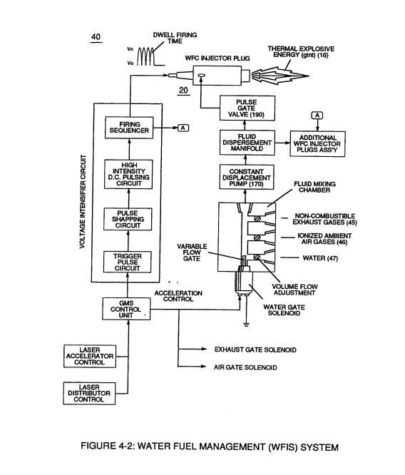
which simply uses Water Fuel Management (WFMS) System fluid-metering system (40) to control gas ignition (16), as illustrated in (40) of Figure (4-2). · Water Fuel Injection System - Page 4
-
(40) of Figure (4-2) · 8-5 - Energy Vectoring (Ev)
-
"FullSystem" development (10) of Figure (4-1) · WFC Development Objectives
-
Figure (10-3 A/B) · Propagating Electrical Stress
-
The figure it sits on · WFC 429 - Illustrations
-
The figure it sits on · WFC 429 - Illustrations
-
The figure it sits on · WFC 429 - Illustrations
-
The figure it sits on · Wobbling Effect
Where it is named · 22
Acceleration Control Circuit (30) 10×
-
Acceleration Control Circuit (30)
This variable response-time (14axx ... 12 ... xxI4n) or signal output (15) of Figure (3-5) is, now, electrically transmitted to Acceleration Control Circuit (30) of Figure (3-5) since Laser Accelerator Assembly (20) of figure (3-10) converts mechanical displacement (9a xxx 9n) to electrical time-response (14a xxx 14n) of Figure (3-7) by linearly moving (forwa …
-
acceleration control circuit (30)
As signal output (15) of figure (4) (14a xxx ... 12 ... xx14n) is being received by acceleration control circuit (30) of Figure (3-5) as to Figure (3-12), circuit (30) converts incoming time-response signal (14a xxx ... 12 ... xx14n) into a variable time-base unipolar pulse (16), as shown in Figure (3-8).
-
circuit (30)
As signal output (15) of figure (4) (14a xxx ... 12 ... xx14n) is being received by acceleration control circuit (30) of Figure (3-5) as to Figure (3-12), circuit (30) converts incoming time-response signal (14a xxx ... 12 ... xx14n) into a variable time-base unipolar pulse (16), as shown in Figure (3-8).
-
Circuit (30)
Circuit (30) electronically and automatically scans output signal-array (14axxx ... 12 ... xx14n) (15) until circuit (30) locates, momentarily registers, and translates response-time (14a xxx ... 12) into a variable unipolar pulse (17/18) of Figure (3-8).
-
circuit (30)
Circuit (30) electronically and automatically scans output signal-array (14axxx ... 12 ... xx14n) (15) until circuit (30) locates, momentarily registers, and translates response-time (14a xxx ... 12) into a variable unipolar pulse (17/18) of Figure (3-8).
-
scanning circuit (30)
The sweeping action of the scanning circuit (30) always starts from position (9a) and moves point (8ax) to point (8axxx) of Figure (3-9) (3-12) until logic-point (12) is detected.
-
circuit (30)
Toggling-time (scanning-time) is directly synchronized to light gate (9) displacement which, in turns, circuit (30) further sets up and establishes a given pulse shape (16) of Figure (3-8).
-
Circuit (30)
Circuit (30) continues to increase pulse width (17axxxx) of Figure (3-8) as the monitored (detected by < scanning) toggling-time (14a xxxx ... 12) increases when logic-point (12) moves farther away from start-position (9a) to stop-position (9n), as further shown in Figure (3-13) as to Figure (3-12).
-
circuit (30)
Finally, circuit (30) reproduces the variable controlled pulse-shape (16) in a continuous repetitive manner (16a xxx 16n) of Figure (3-13) and electrically transmits the resultant pulse-train signal (19) to Analog Voltage Circuit (40), as shown in Figure (3-5).
-
circuit (30)
sets up the scan-rate (toggling) by which signal input (15) of Figure (3-5) is electronically scanned by circuit (30).
Analog Voltage generator (40) 1×
-
accelerated control circuit (30)
The generated digital signal (19) being electrically transmitted from accelerated control circuit (30) of Figure (3-5) is, now, electronically detected, translated, and converted into a analog voltage signal (22) which is continuously proportionate to input signal (19) by Analog Voltage Generator Circuit (40) of Figure (3-5).
Variable Pulse Frequency Generator (70) 1×
-
Acceleration Control Circuit (30)
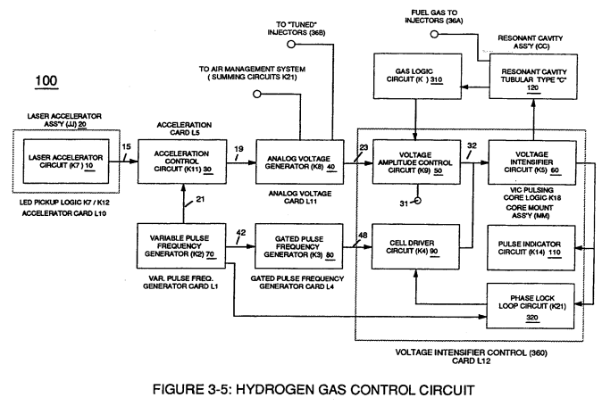
Increasing the number of duty pulses (39a xxx 39n) up to pulse frequency range of 10Khz or above now forms clock signal (21) of Figure (3-5) which, in turns, performs the scanning function of Acceleration Control Circuit (30) of Figure (3-5).
Water Fuel Injection System 5×
-
Secondly, ionized air gases (46a xxx 46n) of Figure (3A) (laser primed ambient air gases having missing electrons) produced by Ambient Air Ionizer (80) of Figure (4) as to Figure (1) and non-combustible gases (45) of Figure (3A) are intermixed with expelling water mist (47a xxx 47n) to form Water-fuel mixture (48) by way of gas mixing disc (34) of Figure (3B) as to (30) of Figure (2A);
-
...which, in turn, not only performs electrical polarization process (160) of Figure (25) undergoing Dielectric Resonant (240) of Figure (30); but, also sets up and triggers Hydrogen Fracturing Process (390) of Figure (41) as to Figure (6) under control state (on demand) via electrical-static spark ignition (49 / 51) of Figure (3B)....rele …
-
WFC injector assembly (10) of Figure (1) as to (30) of Figure (2A) is design variable to be retrofitable by replacing fossil-fuel injector ports affixed to jet engines (see Figure 11), heating systems (Figure 10), rockets engines (Figure 12), or even …
-
Water Fuel Injector (20/30)
Sequential pulsing of Water Fuel Injector (20/30) of Figure (1) as to (40) of Figure (2B) is system activated by Pulse Gate Valve (190) of Figure (1) to further control a predetermined energy-flame (16).
-
Water Fuel Injector Plug (20 / 30)
Water Fuel Injector Plug (20 / 30), as illustrated in (40) of Figure (2B) as to (10) of Figure (1).
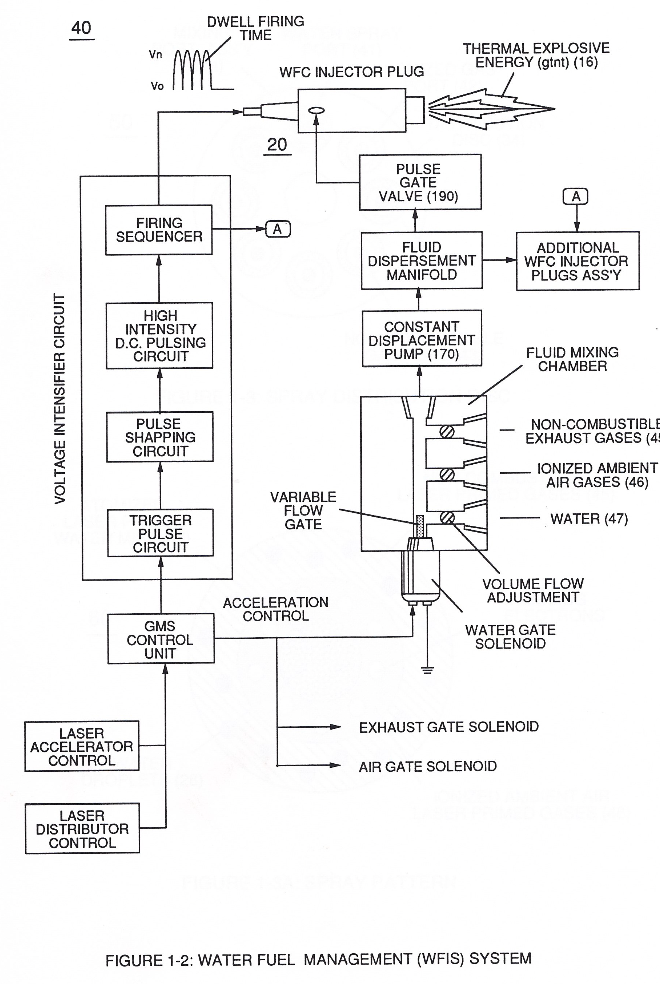
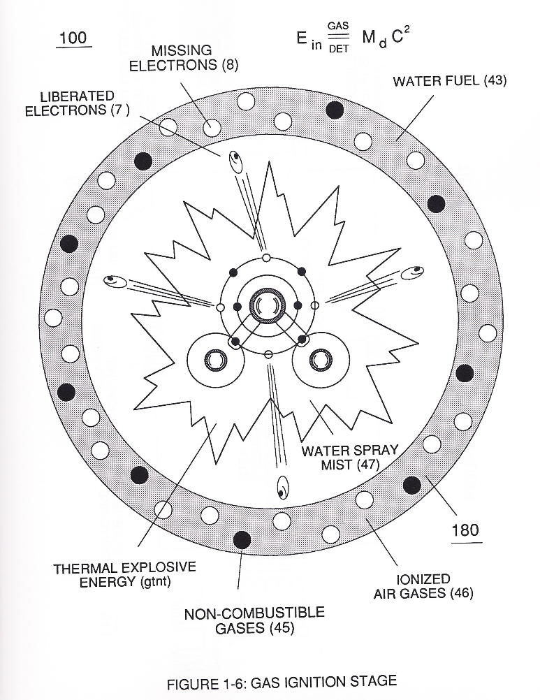
Water Fuel Injection System - Page 1 1×
-
Secondly, ionized air gases (46a xxx 46n) of Figure (4-4) (laser primed ambient air gases having missing electrons) produced by Ambient Air Ionizer (80) of Figure (4-6) as to Figure (4-1) and non-combustible gases (45) of Figure (4-4) are intermixed with expelling water mist (47a xxx 47n) to form Water-fuel mixture (48) by way of gas mixing disc (34) of Figure (4-5) as to (30) of Figure (4-2);
Water Fuel Injection System - Page 4 3×
-
WFC injector assembly (10) of Figure (4-1) as to (30) of Figure (4-2) is design variable to be retrofitable by replacing fossil-fuel injector ports affixed to jet engines (see Figure 4-13)
-
Water Fuel Injector (20/30)
Sequential pulsing of Water Fuel Injector (20/30) of Figure (4-1) as to (40) of Figure (4-2) is system activated by Pulse Gate Valve (190) of Figure (4-1) to further control a predetermined energy-flame (16).
-
Water Fuel Injector Plug (20/30)
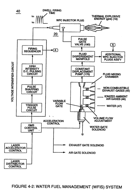
... especially when ionized ambient air gases (400 xxx 46n) and non-combustible gases (45a xxx 45n) are intermixed with water supply (47) prior to entering Water Fuel Injector Plug (20/30), as illustrated in (40) of Figure (4-2) as to (10) of Figure (4-1).
Taper Water Fuel Injectors 1×
-
Basically, then, activation process (590), now, design - forms Water Fuel Injector (20) of Figure (4-2) as to (30) of Figure (4-11) (Memo WFC 423 DA)