Figure (3-26)
Electrical Polarization Process
How it is written
- (3-26) 35×
Drawings 10
-
Figure (3-26) · Voltage Intensifier Circuit (60)
-
Figure (3-26) · Electrically Charged Water Molecule
-
Captioned as this figure · WFC 422DA - Illustrations
-
Figure (25) · Water Fuel Injector (Taper Resonant Cavity Chamber)
-
(160) of Figure (3-26) · Water Fuel Injection System - Page 1
-
(85) of Figure (3-26) · In Application of Usage
-
(160) of Figure (3-26) · In Application of Usage
-
(85) of Figure (3-26) · Resistance (Rs)
-
Captioned as this figure · WFC Exhaust Air Reclaimer
-
(160) of Figure (3-26) · Propagating Electrical Stress
On this figure 15
- 28 Gas Regulator Stage
- 47 Water Mist
- 60 Voltage Intensifier Circuit
- 61 Negative electrical voltage potential
- 65 Voltage Potential
- 68 Water Bath
- 71 Magnetic Field Coupling
- 76 Oxygen Atom
- 77 Hydrogen Atom
- 79 Electrons
- 85 Water Molecule
- 88 Fuel-Gases
- 160 Electrical Polarization Process
- E1 Voltage Zones
- E2 Voltage Zones
Where it is named · 35
Voltage Intensifier Circuit (60) 4×
-
These controlled and variable pulse features are, now, translated to Resonant Charging pulse train (65a xxx 65n) of Figure (3-21) via Unipolar pulse train (64a xxx 64n) of Figure (3-20) during Resonant Action (160) of Figure (3-26) when signal coupling is applied across Resonant Cavity (170) of Figure (3-24) via positive voltage zone (66).
-
Figure (3-26)
-
Figure (3-26)
Electrically Charged Water Molecule 4×
-
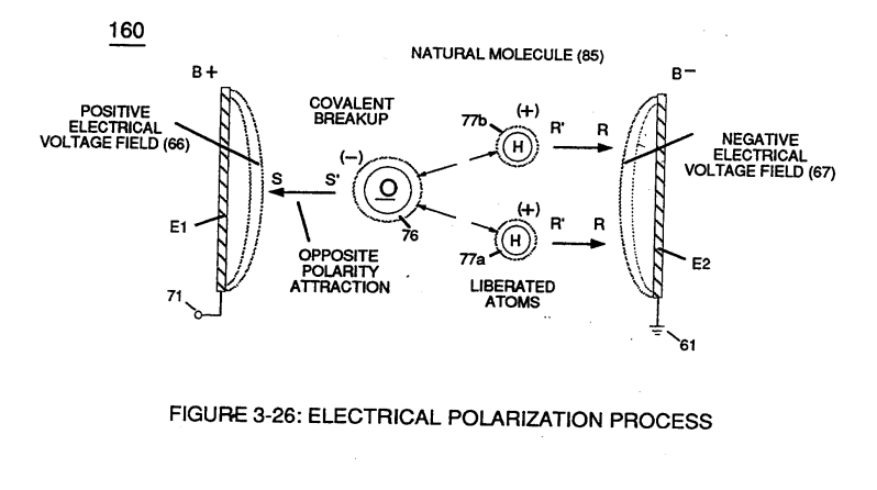
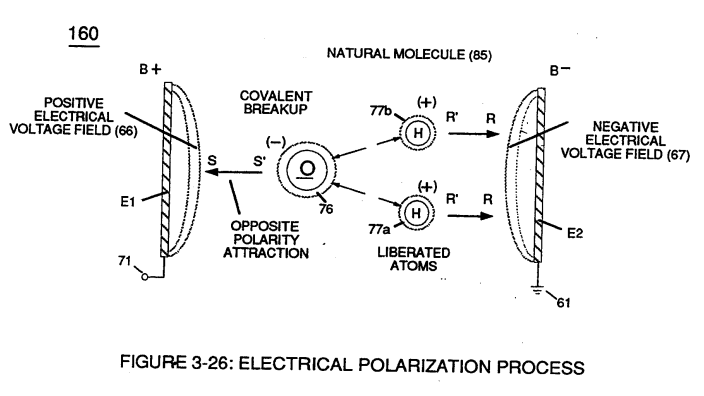
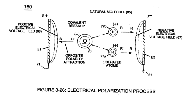
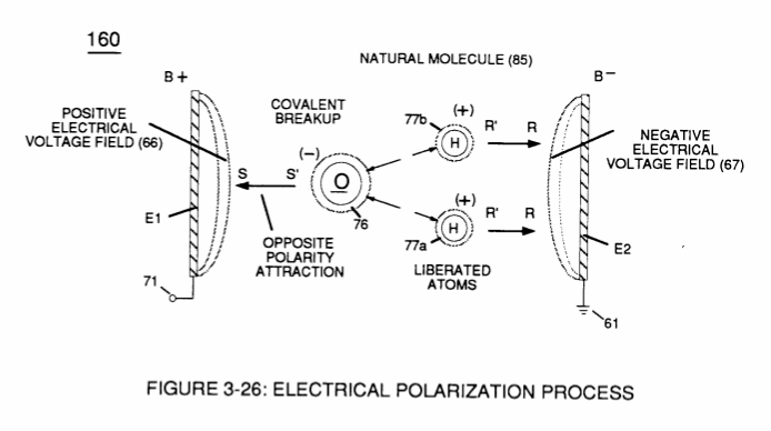
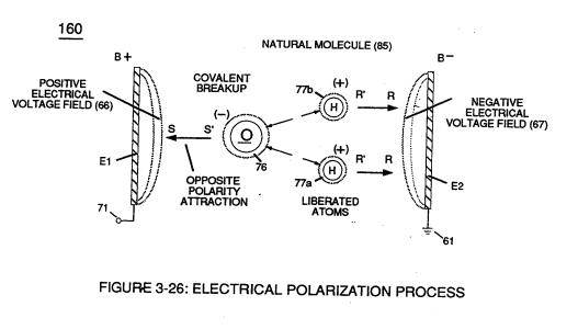
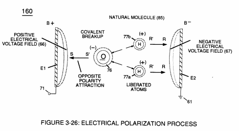
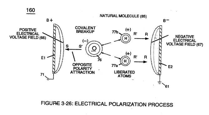
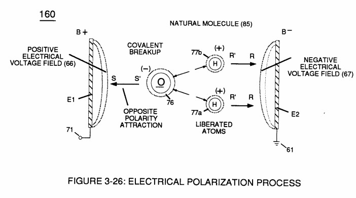
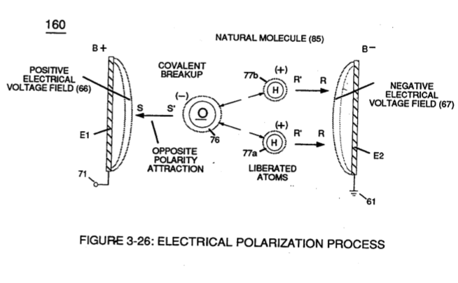
Voltage potential (65) within electrical circuit (60) can cause one or more electrons (79) to be dislodged from the water molecule atom (85) of Figure (3-26) due to opposite electrical polarity attraction (qq') of Figure (3-29) between unlike charged entities, as shown in (160) of Figure (326) as to Newton's and Coulomb's laws of electrical-force.
-
Figure (3-26)
-
Figure (3-26)
Electrical Polarization process 6×
-
Placement of a pulse voltage potential (65) across Excitor plates (E1/E2) (voltage zones 66/67) of Figure (3-29) as to Figure (3-26) while inhibiting and preventing electron flow within voltage intensifier circuit (190) of Figure (3-23) causes water molecule (210) of Figure (3-27) to separate into its component parts (released hyd …
-
… its component parts (released hydrogen and oxygen gases) by pulling away (utilizing opposite attraction forces SS' and RR') its charged water molecule atoms (76n7), as illustrated in (160) of Figure (3-26).
-
Figure (3-26)
-
Once negative electrically charged oxygen atom (76) is dislodged from water molecule (85), covalent bonding (sharing electrons between atoms) ceases to exist, switching-off and disrupting electrical attraction force (qq') between unlike atoms (76/77), as further illustrated in (160) of Figure (3-26).
-
Figure (3-26)
Gas Modulator Process 3×
-
Dissolved air gases (97) of Figure (3-39) being uniformly released from water bath (85) via the Electrical Polarization Process (160) of Figure (3-26) is automatically intermixed with released hydrogen (86) and oxygen (87) gas atoms (also derived from water bath 85) to form Fuel-Gas mixture (88) of Figure (3-24) having a hydrogen gas burn-rate of a …
-
Electrical Polarization Process (160) of Figure (3-26)
Amp Inhibiting Circuit Vs Voltage Enhancement 1×
-
Furthermore, the paired coils-wires opposite voltage potential [positive electrical attraction force (B+) equaling negative electrical force (B-)] [herein called "Electrical Stress" (SS' = RR") as to (160) of Figure (3-26)] are always equal in electrical magnitude/electrical intensity since the wire-length of each coil are the same.
Water Fuel Injection System - Page 1 2×
-
(160) of Figure (3-26)
Water Fuel Injection System - Page 2 2×
-
Water droplets (28a xxx 28n) escaping from spray-mist (47) and exposed to high intensity voltage fields of opposite polarity 33/36) are stimulated to undergo Electrical Polarization Process (160) of Figure (3-26)
-
Figure (3-26)
In Application of Usage 4×
-
The Hydrogen Fracturing Process (390) of Figure (3-42) simply triggers and releases atomic energy (gtnt) from natural water (85) of Figure (3-26) by retarding and preventing the reformation of the water molecule being subjected to sub-critical state (520) of Figure (5-3) during thermal gas ignition (100) of Figure (4-8) as to (70) of Figure (4-5).
-
(85) of Figure (3-26)
-
(160) of Figure (3-26)
Covalent Switch-Off 2×
-
(160) of Figure (3-26) (Memo WFC 422DA)
-
which, when occurring, directly weakens the covalent bonding of the water molecule (q-q') by attenuating the electromagnetic fields of each atom Structure of the water molecule (210) of Figure (3-27) (Memo WFC 422DA) being subjected to and undergoing Electrical Polarization Process (160) of Figure (3-26) (Memo WFC 422DA), as further illustrated in (550) of Figure (5-8).
Water Fuel Injector 1×
-
at activation point (E9b) voltage intensity is increased sufficiently to perform Electrical Polarization Process (160) of Figure (3-26);
Resistance (Rs) 2×
-
... releasing thermal explosive energy (gtnt) (16) of Figure (4-5) on demand from natural water (85) of Figure (3-26) since the dielectric value (Re) of (Eq.9) of Water Fuel (85) is further approximated in Capacitance Equation (Eq.22), as illustrated in (650) of Figure (7-4) as to Tapered Voltage Wave-Guide (720) of Figure (7-11)
-
(85) of Figure (3-26)
WFC Exhaust Air Reclaimer 1×
Propagating Electrical Stress 3×
-
… t dated January 14, 1983 as per WFC Test-Results "Mode of Operability" of using "Voltage Potential" to "Dissociates the Water Molecule" by way of the "Electrical Polarization Process" (160) of Figure (3-26) as so specified under U.S. …
-
Furthermore, the paired coil-wires opposite voltage potential [positive electrical attraction force (B+) - negative electrical attraction force (B-)] [hereinafter called Electrical Stress (SS' - RR') as to (160) of Figure (3-26)] are always equal in electrical magnitude/intensity since the wire-lengths of each coil are the same.
-
(160) of Figure (3-26)