(E7)
(E7)
Where it is first named
thirdly, the resultant moving Water-Fuel mixture (48) of Figure (3B) enters into Voltage Igniter Stage (180) of Figure (3B) and exposed to high intensity voltage fields (33 / 36) (typically 2,000 volts or above @ 10 Khz or above) opposite electrical polarity (E7 / E8)
How it is written
- (E7 / E8) 3× with (E8)
Drawings 9
-
The figure it sits on · Electronic Circuit Design
-
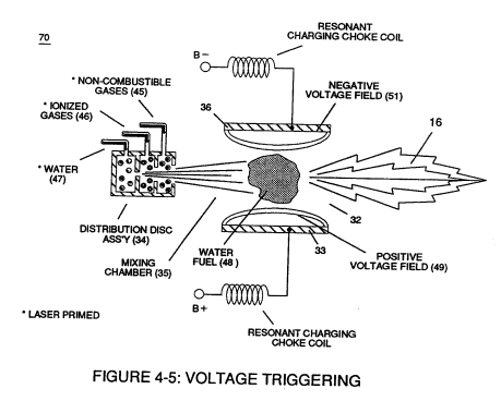
Figure (4-5) · Water Fuel Injection System - Page 1
-
but, also prevents electron flow into destabilizing gas process (180), as so illustrated in Figure (4-5). · Water Fuel Injection System - Page 3
-
The figure it sits on · In Application of Usage
-
Voltage Triggering Process (70) of Figure (4-5) · Voltage Intensifier Coil-Assembly
-
(16) of Figure (4-5) · Resistance (Rs)
-
Figure (4-5) · Capacitance Reactance
-
Figure (4-5) · 8-5 - Energy Vectoring (Ev)
-
The figure it sits on · WFC 427 Illustrations
Where it is named · 3
Water Fuel Injection System 1×
-
thirdly, the resultant moving Water-Fuel mixture (48) of Figure (3B) enters into Voltage Igniter Stage (180) of Figure (3B) and exposed to high intensity voltage fields (33 / 36) (typically 2,000 volts or above @ 10 Khz or above) opposite electrical polarity (E7 / E8)
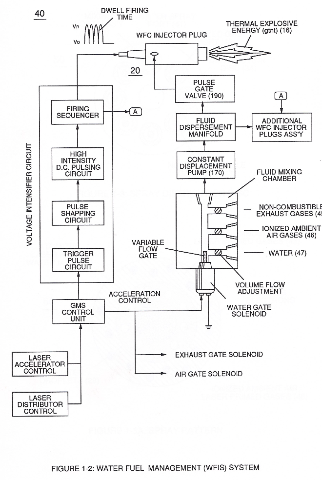
Water Fuel Injector (Taper Resonant Cavity Chamber) 1×
-
... forming a capacitor (E7 / E8) in series with Resonant Charging Chokes (56/57) placed on opposite sides of Resonant Cavity Zone (35) as to Figure (7) and (8) . . . forming a Resonant Pulsing Circuit (110) of Figure (7) with step-up Pulsing Transformer (33/36), as shown in (220) of Figure (18).
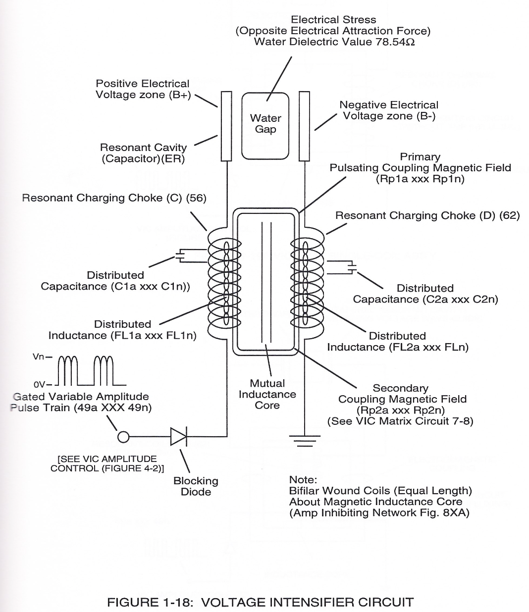
Water Fuel Injection System - Page 1 1×
-
thirdly, the resultant moving Water-Fuel mixture (48) of Figure (4-5) enters into Voltage Igniter Stage (180) of Figure (4-5) and exposed to high intensity voltage fields (33/36) (typically 2,000 volts or above @ 10 Khz or above) of opposite electrical polarity (E7 / E8)