(80)
Circuit
Also written Gated Pulse Frequency Generator Circuit · Gated Pulse Circuit · Hydrogen Fracturing Process · Ambient Air Ionizer · WFC Gas Processor · gated pulse frequency generator
Where it is first named
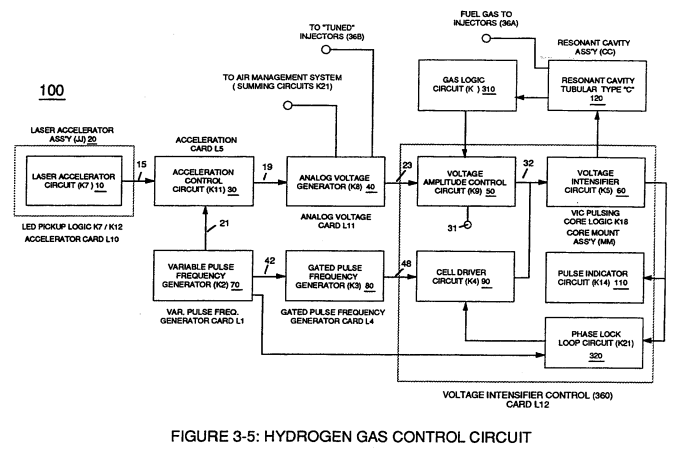
Circuit (70) also produces another independent and separate clock signal (41a xxx 41n) which is electrically transmitted to and become incoming clock signal (42) for Gated Pulse Frequency Generator Circuit (80) of Figure (3-5).
How it is written
- (80) 16×
Drawings 32
-
Figure (3-5) · Acceleration Control Circuit (30)
-
Analog Voltage Circuit (40), as shown in Figure (3-5) · Acceleration Control Circuit (30)
-
Figure (3-5) · Acceleration Control Circuit (30)
-
Figure (3-5) · Analog Voltage generator (40)
-
Figure (3-5) · Laser Distributor
-
Carries this number · WFC 422DA - Illustrations
-
Water Fuel Injection System (10) of Figure (1) · Water Fuel Injector (Taper Resonant Cavity Chamber)
-
(170) of Figure (13) · Water Fuel Injector (Taper Resonant Cavity Chamber)
-
(170) of Figure (13) · Water Fuel Injector (Taper Resonant Cavity Chamber)
-
Fluid Displacement Pump (170) of Figure (13) · Water Fuel Injector (Taper Resonant Cavity Chamber)
-
(80) of Figure (4) · Water Fuel Injector (Taper Resonant Cavity Chamber)
-
Carries this number · Steam Resonator Assembly
-
Ambient Air Ionizer (Gas Processor) (80) of Figure (4-6) · Water Fuel Injection System - Page 3
-
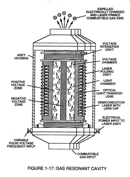
WFC Gas Processor (80) of Figure (1-17) · WFC Development Objectives
-
The forming Argon ion (Ar+) is now exposed to Iron ions (Fe+) (magnetic properties) experiencing and undergoing the same Electron Extraction Process. · Magnetic Gas Lattice
-
Figure (1-8) · Atomic Interaction to Voltage Stimulation
-
Figure (1-8) · Electron Extraction Process
-
Laser activated or laser primed gas ions repel the "dislodged" electrons being consumed as illustrated in Figure (1-8) as to Figure (1-20). · Electron Extraction Process
-
Resonant Cavity Assembly, as illustrated in Figure (1-17) · Electron Extraction Process
-
3-5 Outer Core Bobbin · Voltage Intensifier Coil Assembly
-
The figure it sits on · Electronic Circuit Design
-
The figure it sits on · Electronic Circuit Design
-
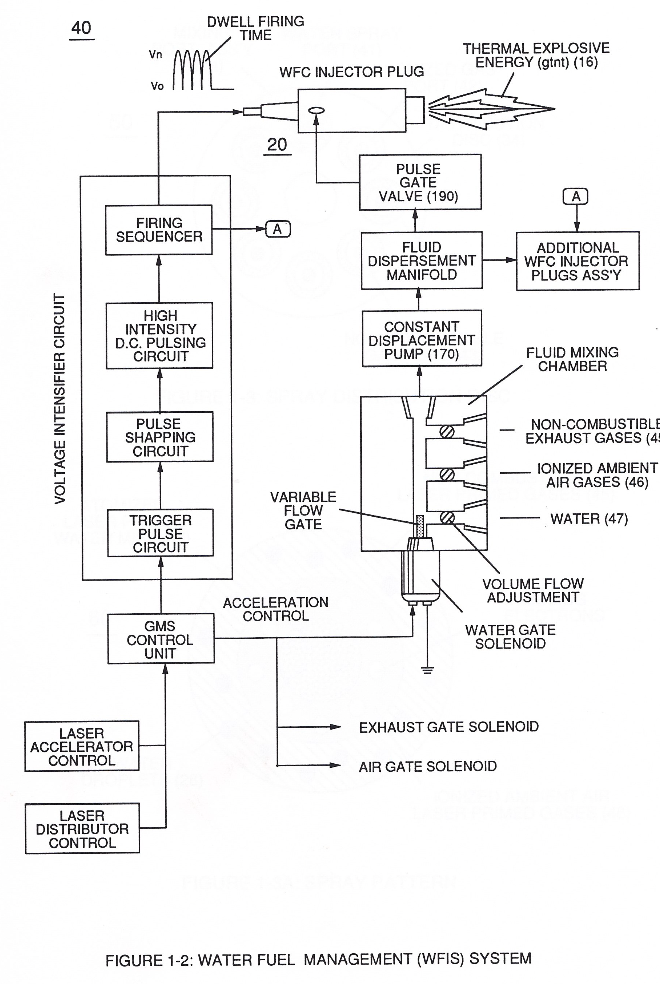
Figure (17) · Water Fuel Injector (Taper Resonant Cavity Chamber)
-
The figure it sits on · Funneling Effect
-
The figure it sits on · Funneling Effect
-
The figure it sits on · Funneling Effect
-
Figure (4-9) · Water Fuel Injection System - Page 2
-
(110) of Figure (4-9) · In Application of Usage
-
(110) of Figure (4-9) · Resistance (Rs)
-
Voltage Intensifier Circuit (110) of Figure (4-9) · WFC Exhaust Air Reclaimer
-
Figure (1-17) · WFC Exhaust Air Reclaimer
-
Blocking Diode (52) of Figure (4-9) · Propagating Electrical Stress
Where it is named · 16
Variable Pulse Frequency Generator (70) 1×
-
Gated Pulse Frequency Generator Circuit (80)
Circuit (70) also produces another independent and separate clock signal (41a xxx 41n) which is electrically transmitted to and become incoming clock signal (42) for Gated Pulse Frequency Generator Circuit (80) of Figure (3-5).
Gated Pulse Frequency generator (80) 3×
-
Gated Pulse Circuit (80)
Gated Pulse Circuit (80) of Figure (3-5) switches "off' and "on" sections of incoming clock signal (42) to form gated pulse (45) which is, in turn, duplicated in succession to produce gated pulse train (46a xxx 46n) of Figure (3-17).
-
circuit (80)
Newly formed gated duty pulse (45) is proportional to the physical change in pulse train (44a xxx 44n) when circuit (80) is adjusted for calibration purposes.
-
circuit (80)
Conversely, opposite pulse shaping occurs when circuit (80) of Figure (3-5) is calibrated in reverse order.
Voltage Intensifier Circuit (60) 1×
-
gated pulse frequency generator (80)
Variable pulse frequency generator (70) of Figure (3-5) varies and adjusts pulse frequency (63) (50% duty cycle pulse) while gated pulse frequency generator (80) of Figure (3-5) varies and adjusts pulse width (54a xxx 54n).
Water Fuel Injection System 3×
-
Ambient Air Ionizer (80)
Secondly, ionized air gases (46a xxx 46n) of Figure (3A) (laser primed ambient air gases having missing electrons) produced by Ambient Air Ionizer (80) of Figure (4) as to Figure (1) and non-combustible gases (45) of Figure (3A) are intermixed with expelling water mist (47a xxx 47n) to form Water-fuel mixture (48) by way of gas mixing disc (34) of Figure (3B) as to (30) of Figure (2A);
-
Hydrogen Fracturing Process (80)
… ses (7a xxx In of Figure 1-8) (see WFC memo 420) to cause the resultant highly energized and mass destabilized combustible gas atoms (93a xxx 93n) of Figure (8) to perform Hydrogen Fracturing Process (80) of Figure (7) when electrostatic force (14/16) thermally ignites (kinetic agitation) destabilized water-fuel mixture (93a xxx 93n) under gas compression... …
-
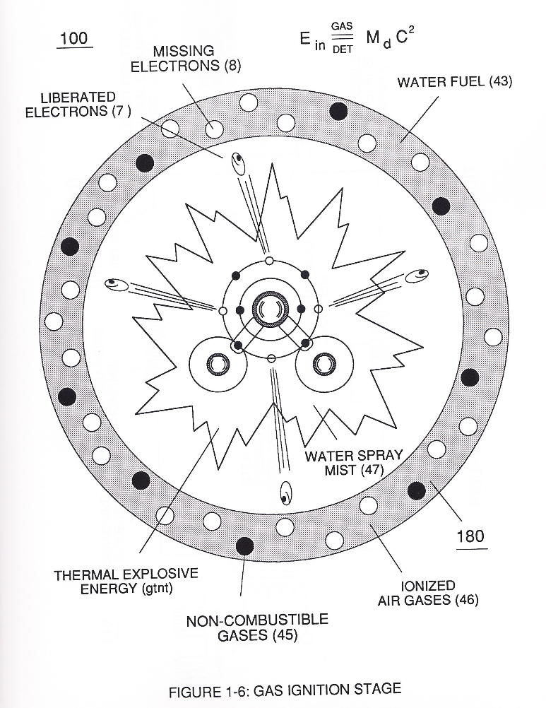
Incoming ambient air gases (5a xxx 5n) become laser primed and ionized when passing through Ambient Air Ionizer (Gas Processor) (80) of Figure (4) as to (10) of Figure (1) since electron extraction circuit (120) of Figure (8) not only captures and consumes ejected electrons (7a cx 7n) of Figure (6); but, also prevents electron flow into destabilizing gas process (180), as so illustrated in Figure (3B).
Water Fuel Injector (Taper Resonant Cavity Chamber) 2×
-
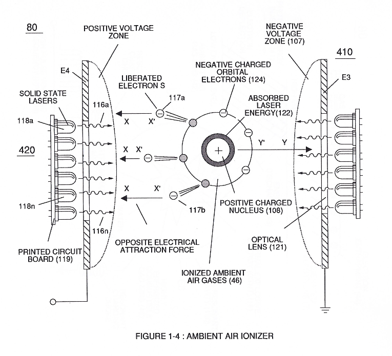
thirdly, by ionizing the released combustible gases by way of Electron Ejection Process (230) of Figure (29) (WFC Memo 422 DA), as further illustrated in (80) of Figure (4);
-
(80) of Figure (4)
Water Fuel Injection System - Page 1 1×
-
Ambient Air Ionizer (80)
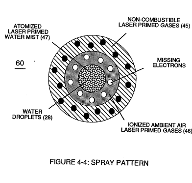
Secondly, ionized air gases (46a xxx 46n) of Figure (4-4) (laser primed ambient air gases having missing electrons) produced by Ambient Air Ionizer (80) of Figure (4-6) as to Figure (4-1) and non-combustible gases (45) of Figure (4-4) are intermixed with expelling water mist (47a xxx 47n) to form Water-fuel mixture (48) by way of gas mixing disc (34) of Figure (4-5) as to (30) of Figure (4-2);
Water Fuel Injection System - Page 3 3×
-
Hydrogen Fracturing Process (80)
… (7a xxx 7n of Figure 1-15) (see WFC memo 420) to cause the resultant highly energized and mass destabilized combustible gas atoms (93a xxx 93n) of Figure (4-10) to perform Hydrogen Fracturing Process (80) of Figure (4-9) when electrostatic force (14/16) thermally ignites (kinetic agitation) destabilized water-fuel mixture (93a xxx 93n) under gas compression
-
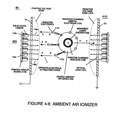
Incoming ambient air gases (5a xxx 5n) become laser primed and ionized when passing through Ambient Air Ionizer (Gas Processor) (80) of Figure (4-6) as to (10) of Figure (4-1) since electron extraction circuit (120) of Figure (4-10) not only captures and consumes ejected electrons (7a xx 7n) of Figure (4-8);
-
Ambient Air Ionizer (Gas Processor) (80) of Figure (4-6)
WFC Development Objectives 2×
-
WFC Gas Processor (80)
Secondly, re-energizing the energy level of the air by the use of WFC Gas Processor (80) of Figure (1-17) by tapping into "Universal" energy by way of particle oscillation as a energy generator, as so illustrated in Energy Pumping Action (520) of Figure (5-3) as to Energy Aperture (570) of Figure (5-10).