(40)
Fluid-Metering System
Also written System · Water Fuel Injector Plug · Analog Voltage Circuit · analog circuit · Analog Voltage Generator Circuit · Analog voltage Generator
Where it is first named
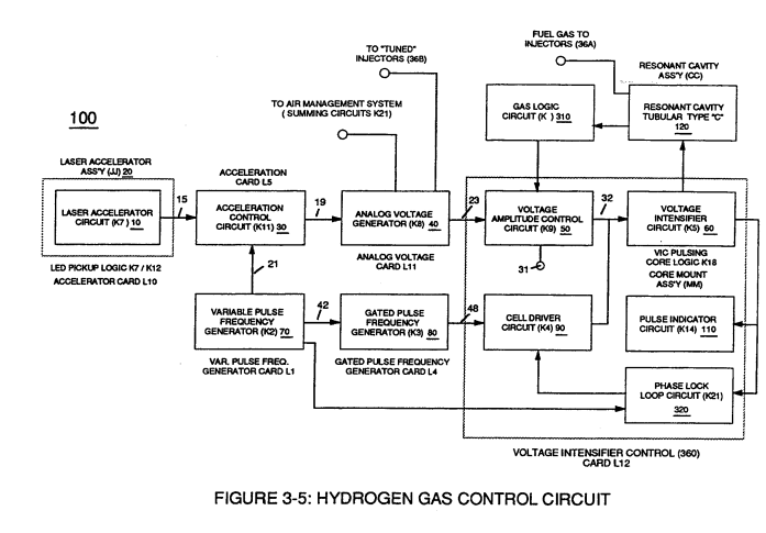
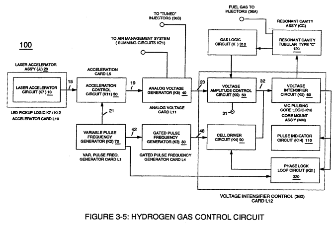
Finally, circuit (30) reproduces the variable controlled pulse-shape (16) in a continuous repetitive manner (16a xxx 16n) of Figure (3-13) and electrically transmits the resultant pulse-train signal (19) to Analog Voltage Circuit (40), as shown in Figure (3-5).
How it is written
- (40) 25×
Drawings 38
-
Stanley A. Meyer Page_7 of 28 · WFC 417 — WFC 417
-
Carries this number · Laser Accelerator Assembly
-
Figure (3-5) · Acceleration Control Circuit (30)
-
Analog Voltage Circuit (40), as shown in Figure (3-5) · Acceleration Control Circuit (30)
-
Figure (3-5) · Acceleration Control Circuit (30)
-
Figure (3-5) · Analog Voltage generator (40)
-
Figure (3-1) · Voltage Amplitude Control Circuit (50)
-
To further prevent voltage fluctuation during resonant action, Phase Lock Loop technique of Pulse Indicator circuit (110) is utilized during pulsing operations. · Resonant Action
-
Figure (3-1) · Laser Distributor
-
Figure (3-5) · Laser Distributor
-
Hydrogen Fuel-Gas Assembly (450) of Figure (3-1) · Operational Parameters
-
Water Fuel Injector Plug (40) of Figure (4-2) · Operational Parameters
-
Carries this number · WFC 422DA - Illustrations
-
Carries this number · WFC 422DA - Illustrations
-
Carries this number · WFC 422DA - Illustrations
-
Carries this number · WFC 422DA - Illustrations
-
Carries this number · Water Fuel Injection System
-
3-4 Inner Core Bobbin · Voltage Intensifier Coil Assembly
-
3-5 Outer Core Bobbin · Voltage Intensifier Coil Assembly
-
3-6 Pulsing Core · Voltage Intensifier Coil Assembly
-
3-8 Multi-Coil Spool · Voltage Intensifier Coil Assembly
-
Carries this number · Voltage Intensifier Coil Assembly
-
Carries this number · Differential Air-Gas Inlet Control
-
2-4 Positive Probe Assembly · Water Fuel Injector Illustrations
-
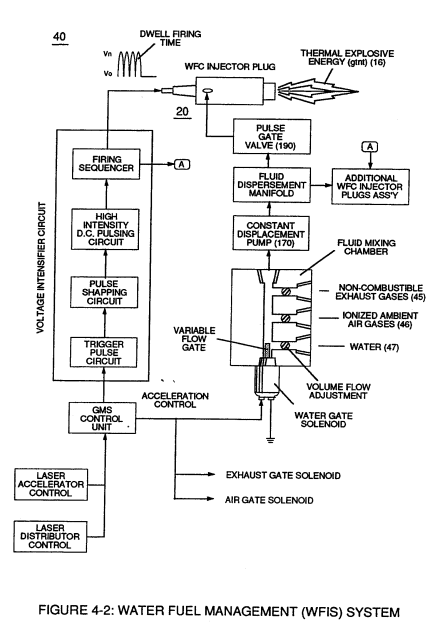
which simply uses Water Fuel Management (WFMS) System fluid-metering system (40) to control gas ignition (16), as illustrated in (40) of Figure (4-2). · Water Fuel Injection System - Page 4
-
(370) of Figure (3-40) · Taper Resonant Capacitor (ERt)
-
Quenching Circuit (370) of Figure (3-40) · Capacitance Reactance
-
(40) of Figure (4-2) · 8-5 - Energy Vectoring (Ev)
-
Figure 4 · Fuel-Gases / Quenching Tube
-
(220) of Figure (18) · Water Fuel Injector (Taper Resonant Cavity Chamber)
-
The figure it sits on · Water Fuel Injector (Taper Resonant Cavity Chamber)
-
The Following Page 1-7 was not available · Water Fuel Injector (Taper Resonant Cavity Chamber)
-
Figure (4-2) · Water Fuel Injection System - Page 1
-
Figure (10-3 A/B) · Propagating Electrical Stress
-
The figure it sits on · WFC 429 - Illustrations
-
The figure it sits on · WFC 429 - Illustrations
-
The figure it sits on · WFC 429 - Illustrations
-
The figure it sits on · Wobbling Effect
Where it is named · 25
Acceleration Control Circuit (30) 2×
-
Analog Voltage Circuit (40)
Finally, circuit (30) reproduces the variable controlled pulse-shape (16) in a continuous repetitive manner (16a xxx 16n) of Figure (3-13) and electrically transmits the resultant pulse-train signal (19) to Analog Voltage Circuit (40), as shown in Figure (3-5).
-
Analog Voltage Circuit (40)
Analog Voltage Circuit (40), as shown in Figure (3-5)
Analog Voltage generator (40) 3×
-
Analog Voltage Generator Circuit (40)
The generated digital signal (19) being electrically transmitted from accelerated control circuit (30) of Figure (3-5) is, now, electronically detected, translated, and converted into a analog voltage signal (22) which is continuously proportionate to input signal (19) by Analog Voltage Generator Circuit (40) of Figure (3-5).
-
analog circuit (40)
In terms of functional-ability and purpose, analog circuit (40) of Figure (3-5) provides a variable (controlled) voltage output (23) in direct relationship to light gate (9) displacement which, in turns, sets up and controls Resonant Action (160) of Figure (3-23) that produces Fuel Gases on demand.
-
Analog circuit (40)
Analog circuit (40) also calibrates both engine idling speed (22ax) and maximum engine R.P.M. (22a xxx 22n) by adjusting and maintaining a predetermined or given low (24) and high voltage levels respectively, as further illustrated in Figure (3-14).
Laser Distributor 1×
-
Analog voltage Generator (40)
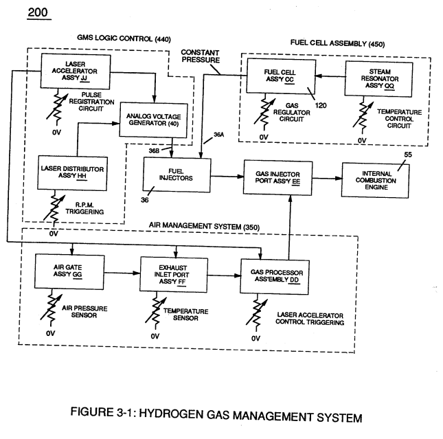
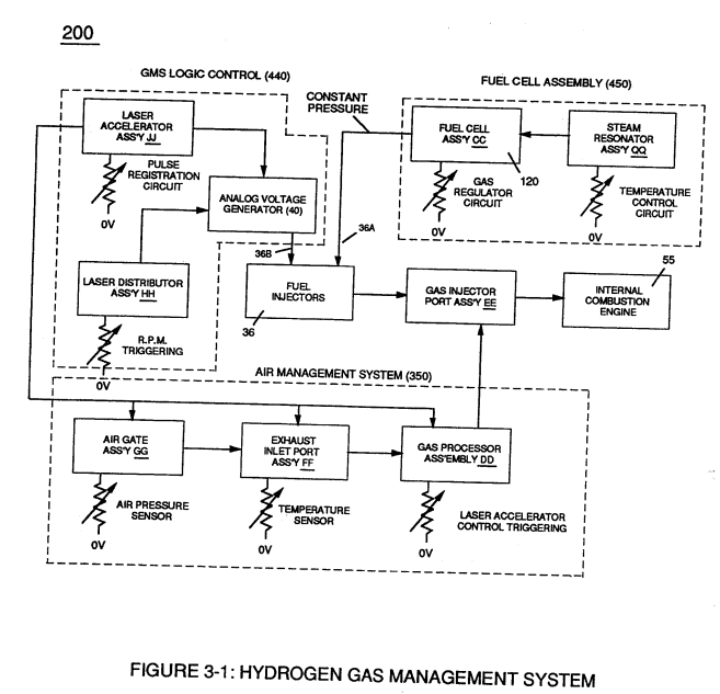
Rotating light-gate triggering circuit assembly (430) sequentially activates Pulse Shaping Generator (440) of Figure (3-4) to produce a constant 50% Duty-cycle Pulse-Train (see Figure 3-16 once again) to Analog voltage Generator (40) of Hydrogen Gas Management System (200) of Figure (3-1) as to Figure (3-5).
Operational Parameters 3×
-
System (40)
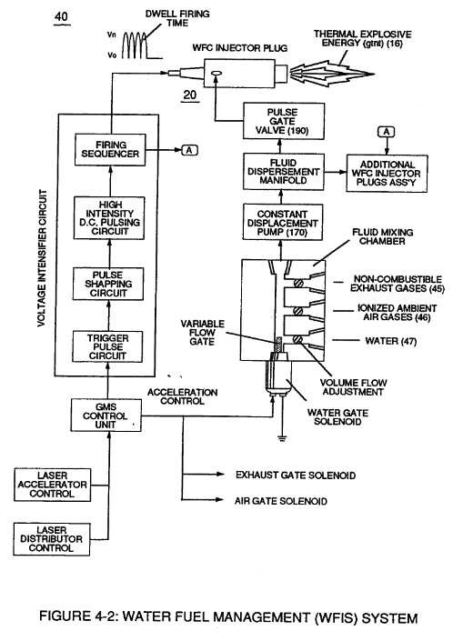
Coupling and subsequently integrating Hydrogen Gas Management (GMS) system (440) with either Hydrogen Fuel-Gas Assembly (450) of Figure (3-1) or Water Fuel Injector Assembly (10) of Figure (4-1) as to Water Fuel Management (WFMS) System (40) of Figure (4-2), now, sets up a full engineering system-approach on how to use Water as a "New" fuel-source.
-
Water Fuel Injector Plug (40)
... especially since Fuel Cell (120) of Figure (3-24) is miniaturized to Water Fuel Injector Plug (40) of Figure (4-2), as further illustrated in WFC memo 423 DA.
-
Water Fuel Injector Plug (40)
Water Fuel Injector Plug (40) of Figure (4-2)
Water Fuel Injection System 7×
-
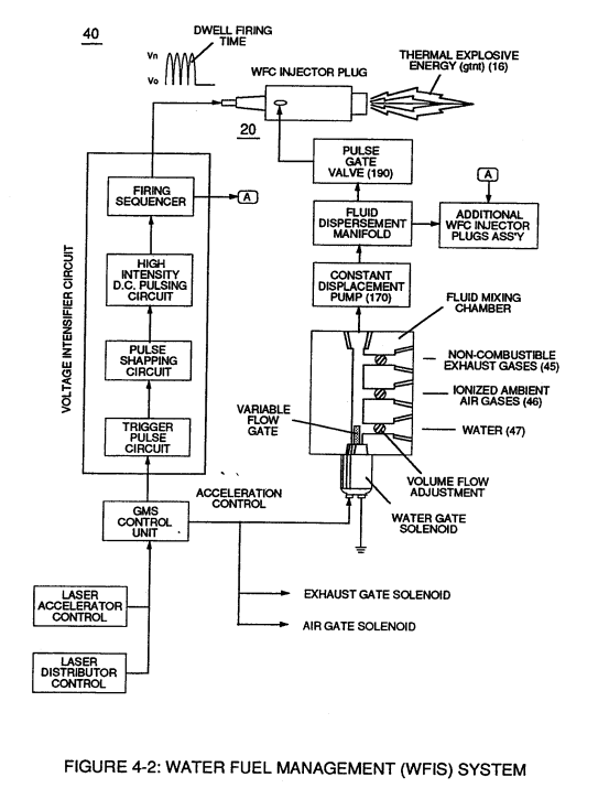
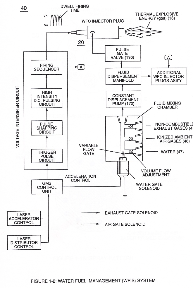
Whereas, Water Fuel Injector Kit (10) of Figure (1) can alternately be used as a self-contained Fuel-unit having no pressurized vessel which converts water directly into thermal explosive energy (gtnt) on demand, as illustrated (10) of Figure (1) as to Figure (40) of Figure (2B 1-2).
-
Operationally, Water Fuel injector assembly (10) of Figure (1) as to (40) of Figure (2B) performs several functions simultaneously to produce thermal explosive energy-yield (gtnt) (16) on demand:
-
fluid-metering system (40)
… ines (see Figure 11), heating systems (Figure 10), rockets engines (Figure 12), or even car spark plugs (130) of Figure (9) which simply uses Water Fuel management (WFMS) system fluid-metering system (40) to control gas ignition (16), as illustrated in (40) of Figure (2B).
-
… ckets engines (Figure 12), or even car spark plugs (130) of Figure (9) which simply uses Water Fuel management (WFMS) system fluid-metering system (40) to control gas ignition (16), as illustrated in (40) of Figure (2B).
-
Sequential pulsing of Water Fuel Injector (20/30) of Figure (1) as to (40) of Figure (2B) is system activated by Pulse Gate Valve (190) of Figure (1) to further control a predetermined energy-flame (16).
-
In essence, then, the Water Fuel Injector system (40) simply processes and converts water into a useful hydrogen fuel on demand at the point of gas ignition...thereby, co-equally or superseding fossil-fuel safety standards...
-
Water Fuel Injector Plug (20 / 30), as illustrated in (40) of Figure (2B) as to (10) of Figure (1).
Water Fuel Injection System - Page 1 2×
-
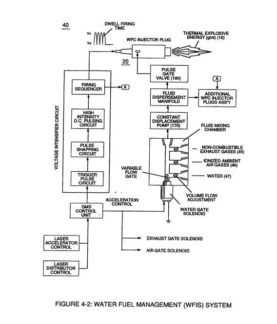
Whereas, Water Fuel Injector Kit (10) of Figure (4-1) can be alternately be used as a self-contained Fuel-unit having no pressurized vessel which converts water directly into thermal explosive energy (gtnt) on demand, as illustrated (10) of Figure (4-1) as to Figure (40) of Figure (4-2).
-
Operationally, Water Fuel injector assembly (10) of Figure (4-1) as to (40) of Figure (4-2) performs several function simultaneously to produce thermal explosive energy-yield (gtnt) (16) on demand:
Water Fuel Injection System - Page 4 5×
-
fluid-metering system (40)
which simply uses Water Fuel Management (WFMS) System fluid-metering system (40) to control gas ignition (16), as illustrated in (40) of Figure (4-2).
-
which simply uses Water Fuel Management (WFMS) System fluid-metering system (40) to control gas ignition (16), as illustrated in (40) of Figure (4-2).
-
Sequential pulsing of Water Fuel Injector (20/30) of Figure (4-1) as to (40) of Figure (4-2) is system activated by Pulse Gate Valve (190) of Figure (4-1) to further control a predetermined energy-flame (16).
-
In essence, then, the Water Fuel Injector system (40) simply processes and converts water into a useful hydrogen fuel on demand at the point of gas ignition
-
... especially when ionized ambient air gases (400 xxx 46n) and non-combustible gases (45a xxx 45n) are intermixed with water supply (47) prior to entering Water Fuel Injector Plug (20/30), as illustrated in (40) of Figure (4-2) as to (10) of Figure (4-1).
8-5 - Energy Vectoring (Ev) 2×
-
The "mode of operability" of determining the "Operational Parameters" of adjusting the thermal explosive energy (gtnt) exiting from nozzle-port (32) of Figure (4-5) as to (40) of Figure (4-2) is directly related to the characteristics of the applied Voltage Pulse Potential (Vpp) Wave-form (s) (Vpwt) and the geometrical configuration of Resonant Cavity (90) of Figure (4-7) as to (730) of Figure (7-12).
-
(40) of Figure (4-2)