(33)
Applied Voltage Intensity
Also written Pulsing Transformer · positive probe · gas regulator
Where it is first named
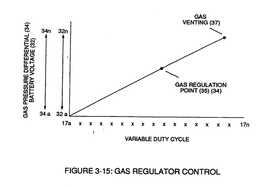
Second regulator stage (28) simply acts and function as a gas regulator (33) by preventing Fuel Gas production beyond a predetermined gas pressure level (34) of Figure (3-15) during Fuel Cell operations and, as such, maintains constant gas pressure to Fuel Injectors (36) of Figure (3-1) regardless of engine performance (R.P.M. response).
How it is written
- (33) 2×
- (33 / 36) 2× with (36) Fuel Injectors
- (33/36) 2× with (36) Fuel Injectors
- (33 /36) 1× with (36) Fuel Injectors
Drawings 34
-
Figure (3-33) · Gas Processor
-
Carries this number · WFC 422DA - Illustrations
-
Carries this number · WFC 422DA - Illustrations
-
Carries this number · Water Fuel Injection System
-
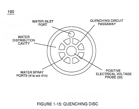
Quenching Disc Structure (190) of Figure (15) · Water Fuel Injector (Taper Resonant Cavity Chamber)
-
Carries this number · Water Fuel Injector (Taper Resonant Cavity Chamber)
-
Carries this number · Funneling Effect
-
(628) of Figure (7-7) · Instant Explosion of Water
-
Carries this number · WFC 426 - Illustrations
-
(Light Emitting Diodes) (1100 xxx 116n) of Figure (3-33) · WFC Exhaust Air Reclaimer
-
Figure (3-15) · Voltage Amplitude Control Circuit (50)
-
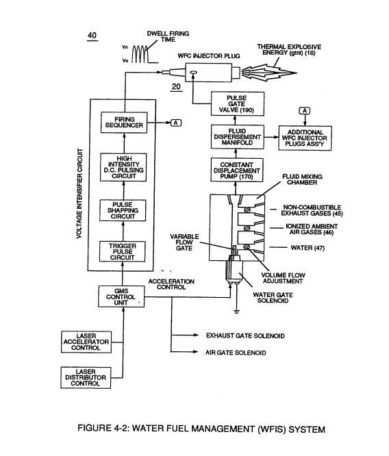
Water Fuel Injector Plug (40) of Figure (4-2) · Operational Parameters
-
The figure it sits on · WFC 422DA - Illustrations
-
3-15 VIC Mount Plate · Voltage Intensifier Coil Assembly
-
The figure it sits on · Electronic Circuit Design
-
(220) of Figure (18) · Water Fuel Injector (Taper Resonant Cavity Chamber)
-
The figure it sits on · Water Fuel Injector (Taper Resonant Cavity Chamber)
-
The Following Page 1-7 was not available · Water Fuel Injector (Taper Resonant Cavity Chamber)
-
Figure (4-5) · Water Fuel Injection System - Page 1
-
Figure (4-2) · Water Fuel Injection System - Page 1
-
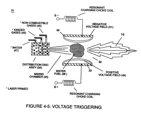
but, also prevents electron flow into destabilizing gas process (180), as so illustrated in Figure (4-5). · Water Fuel Injection System - Page 3
-
which simply uses Water Fuel Management (WFMS) System fluid-metering system (40) to control gas ignition (16), as illustrated in (40) of Figure (4-2). · Water Fuel Injection System - Page 4
-
The figure it sits on · In Application of Usage
-
Voltage Triggering Process (70) of Figure (4-5) · Voltage Intensifier Coil-Assembly
-
(16) of Figure (4-5) · Resistance (Rs)
-
Figure (4-5) · Capacitance Reactance
-
Figure (4-5) · 8-5 - Energy Vectoring (Ev)
-
(40) of Figure (4-2) · 8-5 - Energy Vectoring (Ev)
-
The figure it sits on · WFC 427 Illustrations
-
Figure (10-3 A/B) · Propagating Electrical Stress
-
The figure it sits on · WFC 429 - Illustrations
-
The figure it sits on · WFC 429 - Illustrations
-
The figure it sits on · WFC 429 - Illustrations
-
The figure it sits on · Wobbling Effect
Where it is named · 7
Voltage Amplitude Control Circuit (50) 1×
-
gas regulator (33)
Second regulator stage (28) simply acts and function as a gas regulator (33) by preventing Fuel Gas production beyond a predetermined gas pressure level (34) of Figure (3-15) during Fuel Cell operations and, as such, maintains constant gas pressure to Fuel Injectors (36) of Figure (3-1) regardless of engine performance (R.P.M. response).
Water Fuel Injection System 2×
-
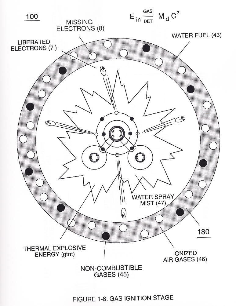
thirdly, the resultant moving Water-Fuel mixture (48) of Figure (3B) enters into Voltage Igniter Stage (180) of Figure (3B) and exposed to high intensity voltage fields (33 / 36) (typically 2,000 volts or above @ 10 Khz or above) opposite electrical polarity (E7 / E8)
-
Energy-Flame temperature is regulated by controlling the volume flow-rate of each fluid mediums (47 / 45/ 46) in direct relationship to applied voltage intensity (33 /36), as further stated in Figure (2B) as to Figure (3B).
Water Fuel Injector (Taper Resonant Cavity Chamber) 2×
-
positive probe (33)
The injected water fuel-droplets (48a xxx 48n), now, surrounds outer surface area of exposed positive probe (33) while entering into Taper Resonant Cavity (180), as illustrated in (70) of Figure (3B) as to Figure (14).
-
Pulsing Transformer (33/36)
... forming a capacitor (E7 / E8) in series with Resonant Charging Chokes (56/57) placed on opposite sides of Resonant Cavity Zone (35) as to Figure (7) and (8) . . . forming a Resonant Pulsing Circuit (110) of Figure (7) with step-up Pulsing Transformer (33/36), as shown in (220) of Figure (18).
Water Fuel Injection System - Page 1 1×
-
thirdly, the resultant moving Water-Fuel mixture (48) of Figure (4-5) enters into Voltage Igniter Stage (180) of Figure (4-5) and exposed to high intensity voltage fields (33/36) (typically 2,000 volts or above @ 10 Khz or above) of opposite electrical polarity (E7 / E8)
Water Fuel Injection System - Page 2 1×
-
applied voltage intensity (33 / 36)
Energy-Flame temperature is regulated by controlling the volume flow-rate of each fluid-mediums (47 / 45 / 46) in direct relationship to applied voltage intensity (33 / 36), as further illustrated in Figure (4-2) as to Figure (4-5).