(28) · also written as a run, 28a xxx 28n
Gas Regulator Stage
Also written regulator stage · applied electrical power · Water droplets · battery supply
Where it is first named
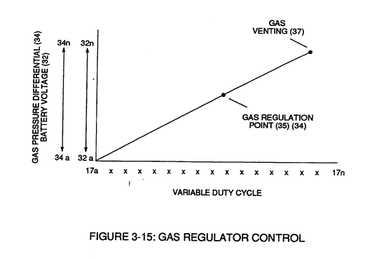
Each regulatory stage (27) and (28) works separately and independent of each other but are! electronically linked or coupled together to produce a common analog signal (32) having a predetermined voltage level (32a xxx), as further shown in Figure (3-15).
How it is written
- (28) 5×
- (28a xxx 28n) 2×
28a xxx 28n is Meyer's shorthand for a run of the same thing: 28a is the first, 28n the last, and the x's stand for however many lie between. Every stage of the run is this one numeral.
Drawings 49
-
Stanley A. Meyer Page_2 of 28 · WFC 417 — WFC 417
-
Stanley A. Meyer Page_3 of 28 · WFC 417 — WFC 417
-
Stanley A. Meyer Page_4 of 28 | · WFC 417 — WFC 417
-
Stanley A. Meyer Page_5 of 28. · WFC 417 — WFC 417
-
Stanley A. Meyer Page_6 of 28 · WFC 417 — WFC 417
-
Stanley A. Meyer Page_8 of 28 · WFC 417 — WFC 417
-
Stanley A. Meyer Page_9 of 28 · WFC 417 — WFC 417
-
Stanley A. Meyer Page 10 of 28 · WFC 417 — WFC 417
-
Stanley A. Meyer Page 12 of 28 · WFC 417 — WFC 417
-
I, is the forward current through LED cluster-Array; Vo¢ is volts applied (typically 5 volts). Stanley A. Meyer Page 14 of 28 · WFC 417 — WFC 417
-
Copyright © 1983 by Stanley A. Meyer Stanley A. Meyer Page15 of 28_ · WFC 417 — WFC 417
-
Copyright © 1983 by Stanley A Meyer Stanley A. Meyer Page16 of 28 · WFC 417 — WFC 417
-
Stanley A. Meyer Page17 of 28 · WFC 417 — WFC 417
-
Page 20 · WFC 417 — WFC 417
-
Stanley A. Meyer Page 20 of 28 · WFC 417 — WFC 417
-
Stanley A. Meyer Page 21 of 28 · WFC 417 — WFC 417
-
Stanley A. Meyer Page. 23 of 28 · WFC 417 — WFC 417
-
Stanley A. Meyer Page 25 of 28 · WFC 417 — WFC 417
-
memo WFC417 · WFC 417 — WFC 417
-
Stanley A. Meyer Page 28 of 28° · WFC 417 — WFC 417
-
Figure (3-28) · Voltage Intensifier Circuit (60)
-
Carries this number · WFC 422DA - Illustrations
-
3-15 VIC Mount Plate · Voltage Intensifier Coil Assembly
-
Carries this number · Electronic Circuit Design
-
Carries this number · Electronic Circuit Design
-
Carries this number · Electronic Circuit Design
-
WFMS Inject Card A2 · WDMS Laser Acceleration Cards
-
Carries this number · Differential Air-Gas Inlet Control
-
Figure (4-4) · Water Fuel Injection System - Page 1
-
(690) of Figure (7-8) · Inductance (FL)
-
Carries this number · Transformer Action
-
equations Eq 28 thru Eq 30 · Electron Bounce Phenomenon
-
Figure (3-15) · Voltage Amplitude Control Circuit (50)
-
Figure (3-6) · Voltage Amplitude Control Circuit (50)
-
Figure (3-6) · Cell Driver Circuit (90)
-
Figure (3-26) · Voltage Intensifier Circuit (60)
-
Figure (3-26) · Electrically Charged Water Molecule
-
The figure it sits on · WFC 422DA - Illustrations
-
The figure it sits on · WFC 422DA - Illustrations
-
The figure it sits on · WFC 422DA - Illustrations
-
3-6 Pulsing Core · Voltage Intensifier Coil Assembly
-
Figure (25) · Water Fuel Injector (Taper Resonant Cavity Chamber)
-
(160) of Figure (3-26) · Water Fuel Injection System - Page 1
-
Figure (3-6) · Water Fuel Injection System - Page 1
-
(85) of Figure (3-26) · In Application of Usage
-
(160) of Figure (3-26) · In Application of Usage
-
(85) of Figure (3-26) · Resistance (Rs)
-
The figure it sits on · WFC Exhaust Air Reclaimer
-
(160) of Figure (3-26) · Propagating Electrical Stress
Where it is named · 7
Voltage Amplitude Control Circuit (50) 4×
-
Each regulatory stage (27) and (28) works separately and independent of each other but are! electronically linked or coupled together to produce a common analog signal (32) having a predetermined voltage level (32a xxx), as further shown in Figure (3-15).
-
regulator stage (28)
Second regulator stage (28) simply acts and function as a gas regulator (33) by preventing Fuel Gas production beyond a predetermined gas pressure level (34) of Figure (3-15) during Fuel Cell operations and, as such, maintains constant gas pressure to Fuel Injectors (36) of Figure (3-1) regardless of engine performance (R.P.M. response).
-
gas regulator stage (28)
In cases where linear voltage (32) drops (descending value) below gas-point (35) then gas regulator stage (28) increases voltage amplitude (32a xxx 32n) (analog voltage) to voltage point (35).
-
applied electrical power (28)
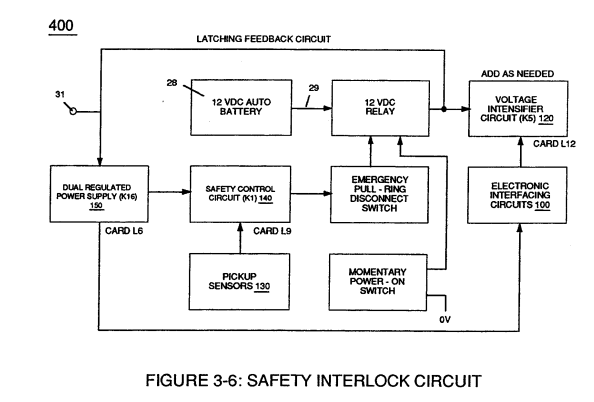
… gases (88) until gas point (34) is either reached or a delay timing circuit activates Safety Control Circuit (14) of Figure (3-6) which, in turns, switches off or disconnects applied electrical power (28) to Fuel Cell electrical system (400) of Figure (3-6).
Cell Driver Circuit (90) 1×
-
battery supply (28)
Only voltage cross-over from regulated power supply (150) of Figure (3-6) to battery supply (28) occurs, as illustrated in Figure (3-6).
Water Fuel Injection System 1×
-
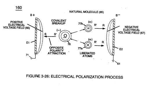
Water droplets (28a xxx 28n) escaping from spray-mist (47) and exposed to high intensity voltage fields of opposite polarity 33/ 36) are stimulated to undergo Electrical Polarization Process (160) of Figure (25)...which not only …
Water Fuel Injection System - Page 2 1×
-
Water droplets (28a xxx 28n)
Water droplets (28a xxx 28n) escaping from spray-mist (47) and exposed to high intensity voltage fields of opposite polarity 33/36) are stimulated to undergo Electrical Polarization Process (160) of Figure (3-26)