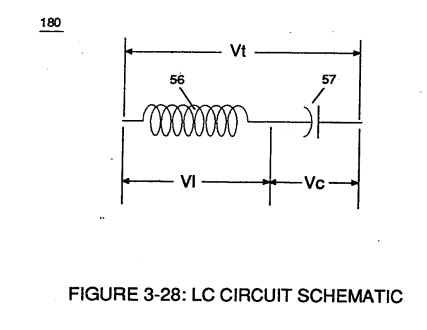
Figure (3-28)
Lc Circuit Schematic
How it is written
- (3-28) 7×
Drawings 4
-
Figure (3-28) · Voltage Intensifier Circuit (60)
-
Ohm's law of LC circuit (180) of Figure (3-28) in series is given by (Eq 5) · Voltage Intensifier Circuit (60)
-
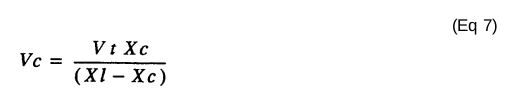
Voltage (Vc) of Figure (3-28) across the capacitor is given by (Eq 7) · Voltage Intensifier Circuit (60)
-
Captioned as this figure · WFC 422DA - Illustrations
On this figure 14
- 25 —
- 49 Voltage Pulse frequency
- 56 Resonant Charging Choke
- 57 Capacitor
- 63 Resonant frequency
- 66 Positive Voltage Potential
- 67 Opposite Polarity
- 68 Water Bath
- 160 Electrical Polarization Process
- 180 Voltage Igniter Stage
- V Voltage Amplitude
- VC Vacuum Gap
- Vt Voltage
- Yo Resonant Voltage Intensity
Where it is named · 7
Voltage Intensifier Circuit (60) 7×
-
Figure (3-28)
-
The value of inductor (56), value of capacitor (57), and the pulse-frequency (63) of voltage (Yo xxx Vn) being applied across the LC circuit determined the impedance of LC circuit (Figure 3-28).
-
Ohm's law of LC circuit (180) of Figure (3-28) in series is given by (Eq 5)
-
Voltage (Vc) of Figure (3-28) across the capacitor is given by (Eq 7)