Figure (3-25)
Resonant Cavity
How it is written
- (3-25) 14×
Drawings 4
-
Figure (3-25) · Voltage Intensifier Circuit (60)
-
Captioned as this figure · WFC 422DA - Illustrations
-
Captioned as this figure · Energy Pumping Action
-
(170) of Figure (3-25) · 8-4 - State Space (Sp)
On this figure 12
- 57 Capacitor
- 72 Delrin Material
- 88 Fuel-Gases
- 92 Electrons
- 93 Water Bath Atoms
- 95 Positive Electrical Charge
- 160 Electrical Polarization Process
- 170 Resonant Cavity
- 240 Dielectric Resonant
- TT' Intensified electrical attraction force
- UU' Electrical Attraction Force
- V Voltage Amplitude
Where it is named · 14
Voltage Intensifier Circuit (60) 3×
-
Figure (3-25)
Resonant Action 6×
-
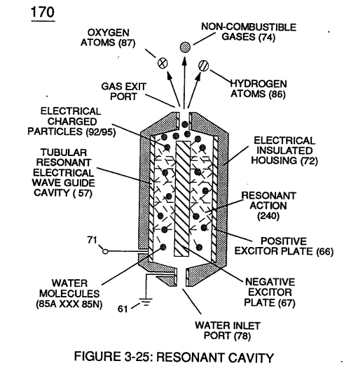
Subjecting and exposing water molecule (85) to even higher voltage levels (xxx Vn) (up to and beyond several thousand volts) causes water bath (91) of Figure (3-30) as to Figure (3-25) to go into a state of ionization by allowing opposite polarity forces (TT') and (UU') to eject one or more electrons (92a xxx 92n) from water bath atoms (93).
-
Figure (3-25)
-
Oscillating and superimposing electrically charged particles unto the Electrical Polarization process at a given pulse-frequency is, now, herein called "Resonant Action", as illustrated in (240) of Figure (3-25).
-
To reach maximum gas-yield (88) resonant cavity (170) of Figure (3-25) is shaped into a tubular structure (typically 0.50 inch diameter tube inserted into 0.75 inch diameter tube having a .0625 concentric air-gap 3 inches long) which functions as a longitudinal wave-guide to enhance particle movement in a lateral or angular displacement to applied voltage fields (66/67).
Gas Processor 2×
-
Voltage fields (106/107) are physically configured (skin effect) by T304 stainless steel material to form voltage plates (E3/E4) of Figure (3-33) which are not only chemically inert to gas ionization process (260) but, also, forms tubular Gas Resonant Cavity (410) of Figure (3-34) having approximately the same size and shape of liquid resonant cavity (170) of Figure (3-25), as illustrated in (270) of Figure (3-34).
-
liquid resonant cavity (170) of Figure (3-25)
8-4 - State Space (Sp) 2×
-
Voltage Tickling of State Space under "Resonant Electrical Stress" without amp influxing while ''Tuning-In' to the dielectric properties of water is herein referred to in this WFC Tech-manual as "Resonant Action," as illustrated graphically in Figure (5-4 A,B,C) as to Resonant Cavity (170) of Figure (3-25) as to Figure (1-13).
-
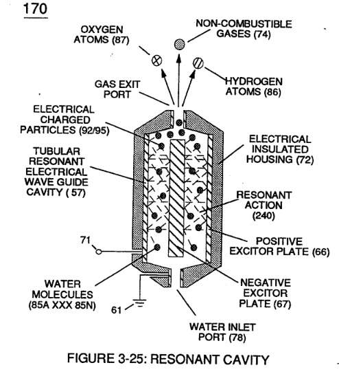
(170) of Figure (3-25)
VIC Switchover Circuit 1×
-
In like manner as to linear cylindrical resonant cavity (730) of Figure (7-12), the Differential Voltage Wave-Guide (1040) of (1010) of Figure (11-1) as to Figure (11-6) is constructed in such a way as to allow a smaller tube to be placed inside a much larger tube having space relationship to allow water to pass there between, as so pictorially shown in (170) of Figure (3-25).