(88)
Fuel-Gases
Also written fuel-gas · metered fuel-gas · Fuel-Gas mixture · gas-yield · higher gas-yield · gas-mixture · gas mixing ratio · Fuel gases
Where it is first named
If gas pressure (34a xx) should exceed gas point (35) during injector off-time, gas pressure release valve (75) of Figure (3-24) (gas venting 37 of Figure 3-15) expels Fuel gases (88) until gas point (34) is either reached or a delay timing circuit activates Safety Control Circuit (14) of Figure (3-6) which, in turns, switches off or disconnects applied electrical power (28) to Fu …
How it is written
- (88) 22×
Drawings 42
-
Figure (3-24) · Voltage Amplitude Control Circuit (50)
-
Figure (3-24) · Electrical Polarization process
-
(340) of Figure (3-38) · Gas Modulator Process
-
(240) of Figure (3-31) · Gas Processor
-
Fuel-gases (88) of figure (3-38) · Diesel Application
-
Carries this number · WFC 422DA - Illustrations
-
Carries this number · WFC 422DA - Illustrations
-
Carries this number · WFC 422DA - Illustrations
-
Carries this number · WFC 422DA - Illustrations
-
Carries this number · WFC 422DA - Illustrations
-
Carries this number · Water Fuel Injection System
-
Carries this number · Water Fuel Injection System - Page 1
-
Figure (3-31) · Water Fuel Injection System - Page 1
-
Figure (3-24) · Inductance (FL)
-
(370) of Figure (3-40) · Taper Resonant Capacitor (ERt)
-
Quenching Circuit (370) of Figure (3-40) · Capacitance Reactance
-
Figure (3-6) · Voltage Amplitude Control Circuit (50)
-
Figure (3-6) · Cell Driver Circuit (90)
-
Figure (3-26) · Voltage Intensifier Circuit (60)
-
Figure (3-25) · Voltage Intensifier Circuit (60)
-
Figure (3-26) · Electrically Charged Water Molecule
-
Figure (3-39) · Resonant Action
-
(340) of Figure (3-38) · Gas Modulator Process
-
In terms of assembly, gas resonant cavity (410), electron extraction circuit (270), optical lens (121) forms gas processor (260) of Figure (3-31). · Gas Processor
-
In terms of assembly, gas resonant cavity (410), electron extraction circuit (270), optical lens (121) forms gas processor (260) of Figure (3-31). · Gas Processor
-
Fuel Cell (120) of Figure (3-24) · Operational Parameters
-
The figure it sits on · WFC 422DA - Illustrations
-
The figure it sits on · WFC 422DA - Illustrations
-
The figure it sits on · WFC 422DA - Illustrations
-
The figure it sits on · WFC 422DA - Illustrations
-
The figure it sits on · WFC 422DA - Illustrations
-
3-6 Pulsing Core · Voltage Intensifier Coil Assembly
-
Figure (25) · Water Fuel Injector (Taper Resonant Cavity Chamber)
-
(160) of Figure (3-26) · Water Fuel Injection System - Page 1
-
Figure (3-6) · Water Fuel Injection System - Page 1
-
The figure it sits on · Energy Pumping Action
-
(85) of Figure (3-26) · In Application of Usage
-
(160) of Figure (3-26) · In Application of Usage
-
(85) of Figure (3-26) · Resistance (Rs)
-
(170) of Figure (3-25) · 8-4 - State Space (Sp)
-
The figure it sits on · WFC Exhaust Air Reclaimer
-
(160) of Figure (3-26) · Propagating Electrical Stress
Where it is named · 22
Voltage Amplitude Control Circuit (50) 1×
-
Fuel gases (88)
If gas pressure (34a xx) should exceed gas point (35) during injector off-time, gas pressure release valve (75) of Figure (3-24) (gas venting 37 of Figure 3-15) expels Fuel gases (88) until gas point (34) is either reached or a delay timing circuit activates Safety Control Circuit (14) of Figure (3-6) which, in turns, switches off or disconnects applied electrical power (28) to Fu …
Electrical Polarization process 1×
-
gas-mixture (88)
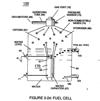
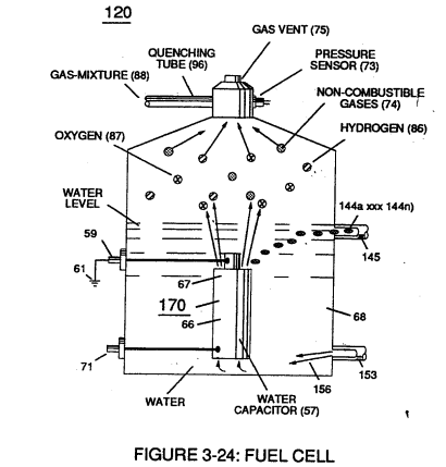
Repetitive duplication of voltage pulse (65a xxx 65n) continues to separate or split apart other water molecules (85a xxx 85n) which, in turns, forms hydrogen (86) and oxygen (87) gas-mixture (88) of Figure (3-24).
Resonant Action 5×
-
higher gas-yield (88)
At resonance, electrical polarization process (160) interacts uniformly with liberated charged particles (92/95) of Figure (3-25) to obtain a even higher gas-yield (88) at maximum voltage deflection (xxx Vn).
-
gas-yield (88)
To reach maximum gas-yield (88) resonant cavity (170) of Figure (3-25) is shaped into a tubular structure (typically 0.50 inch diameter tube inserted into 0.75 inch diameter tube having a .0625 concentric air-gap 3 inches long) which functions as a longitudinal wave-guide to enhance particle movement in a lateral or angular displacement to applied voltage fields (66/67).
-
fuel-gas (88)
The resultant fuel-gas (88) is, now, transferred through Quenching Tube (96) of Figure (3-41) to, through and beyond Fuel Injectors (36) of Figure (3-1) for Hydrogen gas utilization.
-
Fuel-Gases (88)
Under normal gas ignition or gas combustion process, released Fuel-Gases (88) of Figure (3-39) as to Figure (3-24) nets a thermal explosive energy yield (gtnt) of approximately 2 1/2 rimes greater than gasoline.
Gas Modulator Process 10×
-
Fuel-Gas mixture (88)
… the Electrical Polarization Process (160) of Figure (3-26) is automatically intermixed with released hydrogen (86) and oxygen (87) gas atoms (also derived from water bath 85) to form Fuel-Gas mixture (88) of Figure (3-24) having a hydrogen gas burn-rate of approximately 47 centimeters per seconds (cm/see) in ambient air, as illustrated in (330) of Figure (3-37).
-
Fuel-Gas (88)
Volatility of hydrogen fuel-mixture or Fuel-Gas (88) is reduced from 325 cm/sec. to approximately 47 cm/sec. since ambient air gases (97) (dissolved air gases in water) is primarily composed of non-combustible gases (74) (such as nitrogen, argon, and other non-burnable gases) of Figure (3-39) which acts and performs as a "Gas Modulator" during thermal gas ignition (98), as illustrated in (320) of Figure (3-36).
-
gas mixing ratio (88)
… (160) of Figure (3-26) in conjunction with the use of chemically inert stainless steel (T304 material) voltage zones (E1 / E2) submerged in natural water (68) sustains and maintains gas mixing ratio (88) by simply preventing the consumption of both the hydrogen (86) and oxygen (87) gases by way of not encouraging "electrical heat" or "chemical interaction" associated with amp consumption.
-
gas-mixture (88)
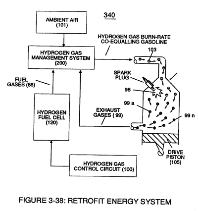
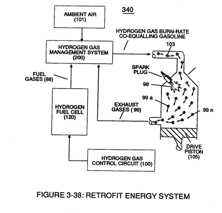
To further reduce hydrogen burn-rate (330) of Figure (3-37) to other fossil-fuel burning levels, additional non-combustible gases (99a xxx 99n) (supplied via ambient air 101) is added to gas-mixture (88) by way of gas ignition process (98) occurring inside internal combustion engine (55) piston cylinder (102), as illustrated in (340) of Figure (3-38).
-
fuel-gas (88)
As fuel-gas (88) enters into engine cylinder (102) and is exposed to thermal gas ignition process (98), the incoming and moving fuel-gases (88) are converted into non-combustible gases (99) (gases passing through the gas combustion process) since both the hydrogen (86) and oxygen (87) gas atoms are being consumed during the formation of superheated water mist (103)
-
fuel-gases (88)
As fuel-gas (88) enters into engine cylinder (102) and is exposed to thermal gas ignition process (98), the incoming and moving fuel-gases (88) are converted into non-combustible gases (99) (gases passing through the gas combustion process) since both the hydrogen (86) and oxygen (87) gas atoms are being consumed during the formation of superheated water mist (103)
-
fuel-gas (88)
In terms of operability and performance, gas modulator process (320) continues to allow a conventional internal combustion engine (55) to run on ambient air gases; while, fuel-gas (88) not only cuts back and reduces oxygen extraction form ambient air (101) but produces a environmentally safe exhaust gases since non-combustible gases (99/74) from both ambient air gases (101) and Fue …
-
Fuel-Gas (88)
… nly cuts back and reduces oxygen extraction form ambient air (101) but produces a environmentally safe exhaust gases since non-combustible gases (99/74) from both ambient air gases (101) and Fuel-Gas (88) are thermally inert to gas ignition process (98).
Gas Processor 2×
-
Fuel-Gases (88)
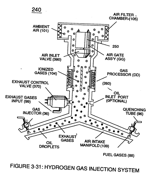
To obtain higher energy-yields beyond the normal gas combustion process, ionized ambient air gases (104) of Figure (3-31) is, now, exposed to and intermixed with Fuel-Gases (88) prior to thermal gas ignition (98) of Figure (3-38), as illustrated in (240) of Figure (3-31).
-
metered fuel-gas (88)
… tical gas atoms (104a xxx 104n) are directed onward through air intake manifold (109) of Figure (3-31) to and beyond both exhaust gas metering port (370) and injector port (36) where metered fuel-gas (88), metered exhaust gases (99), and metered sub-critical gas atoms (104a xxx 104n) forms gas-mixture (103) entering engine cylinder (102), as illustrated in (240) of Figure (3-31) as to (340) of Figure …
Laser Distributor 1×
-
Fuel-Gases (88)
… -gate (141) of Figure (3-44) rotates in the same direction of Spark-rotor (142) and being displaced opposite to rotor blade (142), allowing intermixed processed ambient air gases (101) and Fuel-Gases (88) to enter engine cylinder (102) of Figure (3-38), as illustrated in Injector Control Circuit (300) of Figure (3-4).
Diesel Application 2×
-
Fuel-gases (88)
By simply adjusting Fuel-gases (88) of figure (3-38) burn-rate (330) of Figure (3-37) from (43 - 37 cm/s) (Gasoline) to (40 - 35 cm/s) (Diesel) burning levels, now, allows WFC Hydrogen Gas Management System to be directly retrofitted t …