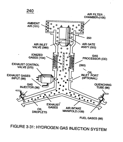
Figure (3-31)
Hydrogen Gas Injection System
Also written Laser Interaction
How it is written
- (3-31) 11×
Drawings 4
-
In terms of assembly, gas resonant cavity (410), electron extraction circuit (270), optical lens (121) forms gas processor (260) of Figure (3-31). · Gas Processor
-
In terms of assembly, gas resonant cavity (410), electron extraction circuit (270), optical lens (121) forms gas processor (260) of Figure (3-31). · Gas Processor
-
(240) of Figure (3-31) · Gas Processor
-
Figure (3-31) · Water Fuel Injection System - Page 1
On this figure 14
- 36 Fuel Injectors
- 88 Fuel-Gases
- 99 Non-Combustible Gases
- 102 Engine Cylinder
- 103 Superheated Water Mist
- 104 Gas Atom
- 106 Positive electrical voltage field
- 109 Air Intake Manifold
- 121 Optical Lens
- 240 Dielectric Resonant
- 260 Ionized Gas Process
- 270 Electron Extraction Circuit
- 370 Quenching Circuit
- 410 Gas Resonant Cavity
Where it is named · 11
Gas Processor 9×
-
Figure (3-31)
-
Once electron ejection occurs, the liberated and free floating electrons (117a xxx 117n) continue to migrate toward positive voltage zone (106); whereas, the newly formed ionized gas atom (having missing electrons) (104) continues to move onward and through air intake manifold (109) of Figure (3-31) to engine cylinder (102) of Figure (3-38).
-
air intake manifold (109) of Figure (3-31)
-
The resultant and newly formed sub-critical gas atoms (104a xxx 104n) are directed onward through air intake manifold (109) of Figure (3-31) to and beyond both exhaust gas metering port (370) and injector port (36) where metered fuel-gas (88), metered exhaust gases (99), and metered sub-critical gas atoms (104a xxx 104n) forms gas-mixture …
-
(240) of Figure (3-31)
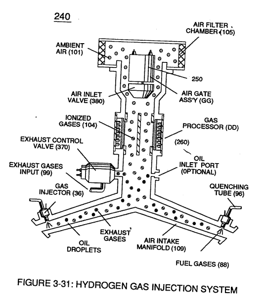
Water Fuel Injection System - Page 1 2×
-
Figure (3-31)