(E2)
Voltage Zones
Also written Electrical Voltage-Plates · applied voltage fields · Excitor-array · negative voltage-plate · voltage-plate · "negative" electrical voltage field · opposite polarity voltage zone · stainless steel voltage plates and 3 more
Where it is first named
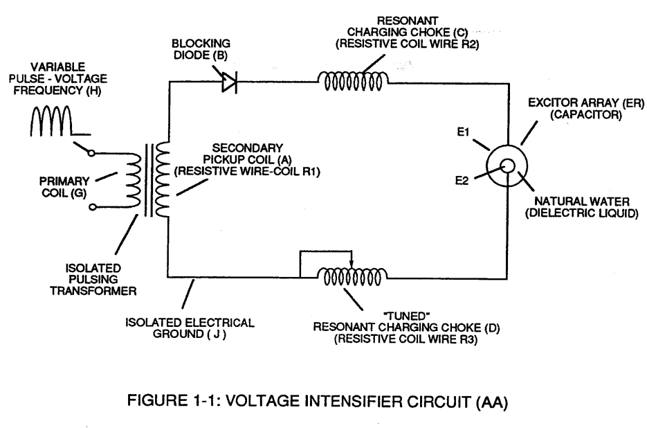
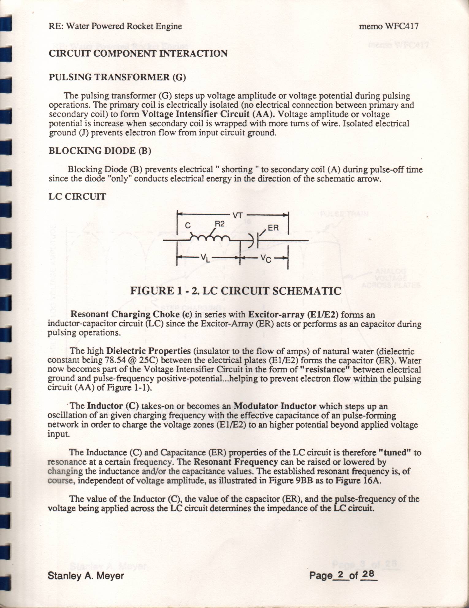
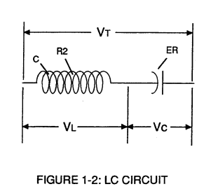
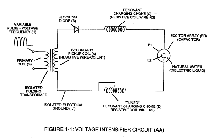
Resonant Charging Choke (c) in series with Excitor-array (E1/E2) forms an inductor-capacitor circuit (LC) since the Excitor-Array (ER) acts or performs as an capacitor during pulsing operations.
How it is written
- (E1/E2) 16× with (E1) Voltage Zones
- (E2) 6×
- (66-El/67-E2) 1× with (66) Positive Voltage Potential, (El) Applied voltage fields, (67) Opposite Polarity
- (E1 / E2) 1× with (E1) Voltage Zones
- (E1/E2 - E9/E10) 1× with (E1) Voltage Zones, (E9) Capacitor, (E10) Capacitor
Drawings 53
-
Stanley A. Meyer Page_2 of 28 · WFC 417 — WFC 417
-
Stanley A. Meyer Page_6 of 28 · WFC 417 — WFC 417
-
Stanley A. Meyer Page 12 of 28 · WFC 417 — WFC 417
-
Inductor (D) in relationship to inductor (C) electrically balances the opposite voltage electrical potential across voltage zones (E1/E2). · Dual-inline RLC Network
-
(E1/E2) of Figure (1-1) page (1-13) · Taper Resonant Capacitor (ERt)
-
LC CIRCUIT Figure 1-2. LC Circuit Schematic · CIRCUIT COMPONENT INTERACTION
-
LC CIRCUIT Figure 1-2. LC Circuit Schematic · CIRCUIT COMPONENT INTERACTION
-
Figure (1-2) · LC Circuit
-
Figure (3-26) · Voltage Intensifier Circuit (60)
-
In both cases, electrical charge deflection or movement is directly related to applied voltage (65). · Voltage Dynamics
-
Ions or particle mass having the same or like electrical charges will move away from one another, as illustrated in (220) of Figure (3-29). · Voltage Dynamics
-
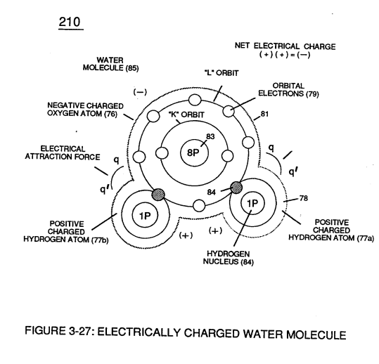
Figure (3-29) · Electrically Charged Water Molecule
-
Figure (3-26) · Electrically Charged Water Molecule
-
The figure it sits on · WFC 422DA - Illustrations
-
The figure it sits on · WFC 422DA - Illustrations
-
The figure it sits on · Water Fuel Injection System
-
The figure it sits on · Electronic Circuit Design
-
Water Fuel Injection System (10) of Figure (1) · Water Fuel Injector (Taper Resonant Cavity Chamber)
-
Figure (25) · Water Fuel Injector (Taper Resonant Cavity Chamber)
-
(160) of Figure (3-26) · Water Fuel Injection System - Page 1
-
(85) of Figure (3-26) · In Application of Usage
-
(160) of Figure (3-26) · In Application of Usage
-
"Voltage Intensity of Opposite Potential" (600) of Figure (6-3) · Voltage Intensifier Coil-Assembly
-
The figure it sits on · WFC 425 - Illustrations
-
The figure it sits on · VIC Matrix Circuit
-
Figure (1-1) (Memo WFC 420) · Instant Explosion of Water
-
(T2) of Figure (7-8) · Instant Explosion of Water
-
Figure (7-8) · Resistance (Rs)
-
(85) of Figure (3-26) · Resistance (Rs)
-
(690) of Figure (7-8) · Resistance (Rs)
-
(600) of Figure (6-3) · Inductance (FL)
-
(690) of Figure (7-8) · Inductance (FL)
-
(600) of Figure (6-3) · Inductance (FL)
-
(690) of Figure (7-8) · Capacitance (Cd)
-
(690) of Figure (7-8) · Inductance Reactance (Rs - Cd - FL)
-
Figure (7-8) · Inductance Reactance (Rs - Cd - FL)
-
(690) of Figure (7-8) · Taper Resonant Capacitor (ERt)
-
690 of Figure 7-8 · Circuit Resistance
-
Voltage Dynamics (220) of Figure (3-29) · Electron Bounce Phenomenon
-
(52) of Figure (7-8) · Electron Bounce Phenomenon
-
The figure it sits on · Dual Switchover Circuit
-
The figure it sits on · 8-1 - Propagating "Resonant Action" By Voltage Tickling of State Space
-
(690) of Figure (7-8) · 8-2 - Traveling Voltage Wave-Guides
-
(52) of Figure (7-8) · 8-3 - Electrical Voltage-Pulse Wave-Transmission
-
(Cp) of Figure (7-8) · 8-4 - State Space (Sp)
-
(690) of Figure (7-8) · 8-6 - VIC Voltage Sync-Pulse Circuit
-
(Cp) of (7-8) · 8-6 - VIC Voltage Sync-Pulse Circuit
-
The figure it sits on · WFC Exhaust Air Reclaimer
-
Voltage Dynamics (220) of Figure (3-29) · WFC Exhaust Air Reclaimer
-
(690) of Figure (7-8) · Propagating Electrical Stress
-
(160) of Figure (3-26) · Propagating Electrical Stress
-
Figure (1-1) · Propagating Electrical Stress
-
The figure it sits on · WFC 429 - Illustrations
Where it is named · 25
WFC 417 — WFC 417 6×
-
Excitor-array (E1/E2)
Resonant Charging Choke (c) in series with Excitor-array (E1/E2) forms an inductor-capacitor circuit (LC) since the Excitor-Array (ER) acts or performs as an capacitor during pulsing operations.
-
The high Dielectric Properties (insulator to the flow of amps) of natural water (dielectric constant being 78.54 @ 25C) between the electrical plates (E1/E2) forms the capacitor (ER). Water now becomes part of the Voltage Intensifier Circuit in the form of "resistance" between electrical ground and pulse-frequency positive-potential...helping to prevent electron flow within the pulsing circuit (AA) of Figure 1-1).
-
'The Inductor (C) takes-on or becomes an Modulator Inductor which steps up an oscillation of an given charging frequency with the effective capacitance of an pulse-forming network in order to charge the voltage zones (E1/E2) to an higher potential beyond applied voltage input.
-
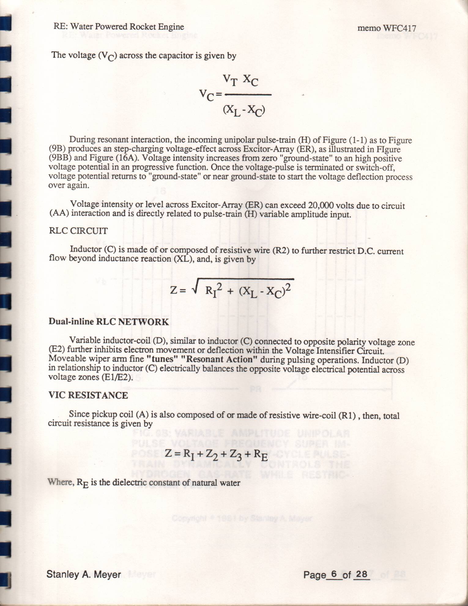
Variable inductor-coil (D), similar to inductor (C) connected to opposite polarity voltage zone (E2) further inhibits electron movement or deflection within the Voltage Intensifier Circuit. Moveable wiper arm fine "tunes" "Resonant Action" during pulsing operations. Inductor (D) in relationship to inductor (C) electrically balances the opposite voltage electrical potential across voltage zones (E1/E2).
-
Variable inductor-coil (D), similar to inductor (C) connected to opposite polarity voltage zone (E2) further inhibits electron movement or deflection within the Voltage Intensifier Circuit. Moveable wiper arm fine "tunes" "Resonant Action" during pulsing operations. Inductor (D) in relationship to inductor (C) electrically balances the opposite voltage electrical potential across voltage zones (E1/E2).
-
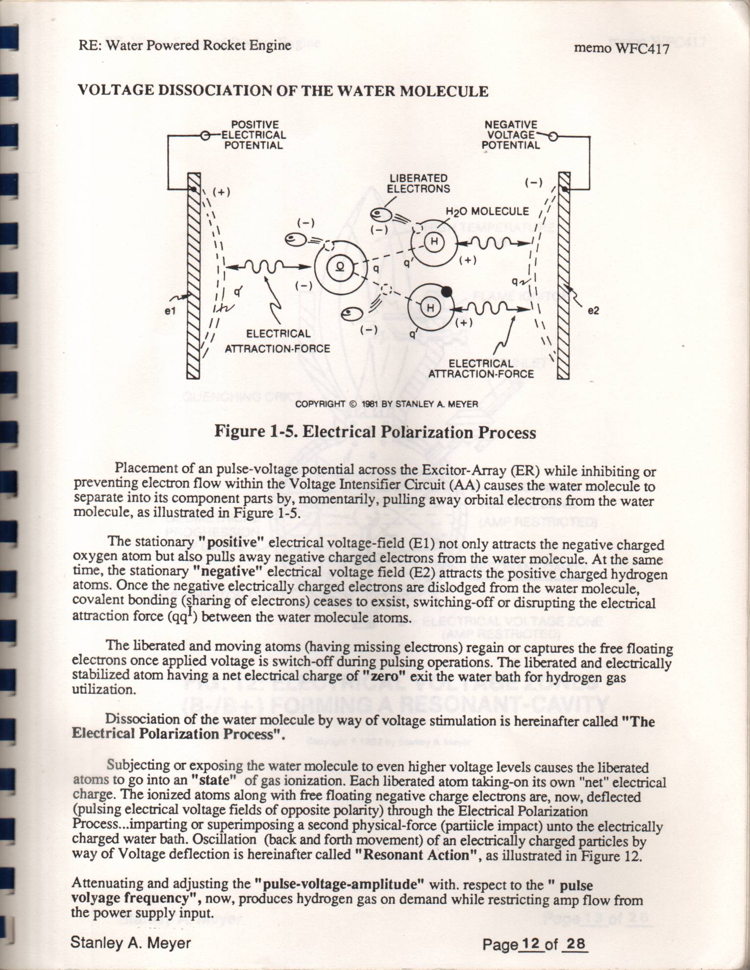
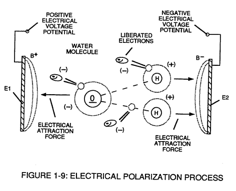
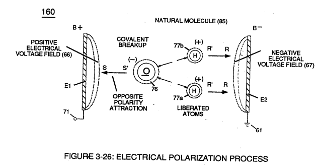
… At the same time, the stationary "negative" electrical voltage field (E2) attracts the positive charged hydrogen atoms. …
LC Circuit 3×
-
Excitor-array (E1/E2)
Resonant Charging Choke (C) in series with Excitor-array (E1/E2) forms an inductor-capacitor circuit (LC) since the Excitor-Array (ER) acts or performs as an capacitor during pulsing operations, as illustrated in Figure (1-2) as to Figure (1-1).
-
electrical plates (E1/E2)
The Dielectric Properties (insulator to the flow of amps) of natural water (dielectric constant being 78.54 @ 25c) between the electrical plates (E1/E2) forms the capacitor (ER).
-
voltage zones (E1/E2)
The Inductor (C) takes on or becomes an Modulator Inductor which steps up an oscillation of an given charging frequency with the effective capacitance of an pulse-forming network in order to charge the voltage zones (E1/E2) to an higher potential beyond applied voltage input.
Dual-inline RLC Network 2×
-
opposite polarity voltage zone (E2)
Variable inductor-coil (D), similar to inductor (C) connected to opposite polarity voltage zone (E2) further inhibits electron movement or deflection within the Voltage Intensifier Circuit.
-
voltage zones (E1/E2)
Inductor (D) in relationship to inductor (C) electrically balances the opposite voltage electrical potential across voltage zones (E1/E2).
Voltage Dissociation of The Water Molecule 1×
-
"negative" electrical voltage field (E2)
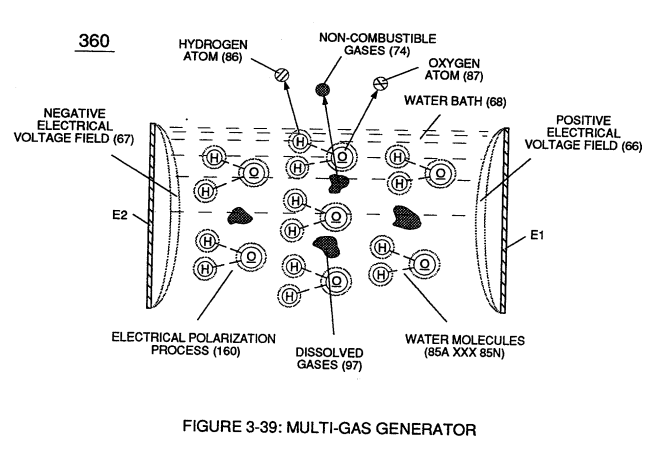
At the same time, the stationary "negative" electrical voltage field (E2) attracts the positive charged hydrogen atoms.
Electrical Polarization process 2×
-
Excitor plates (E1/E2)
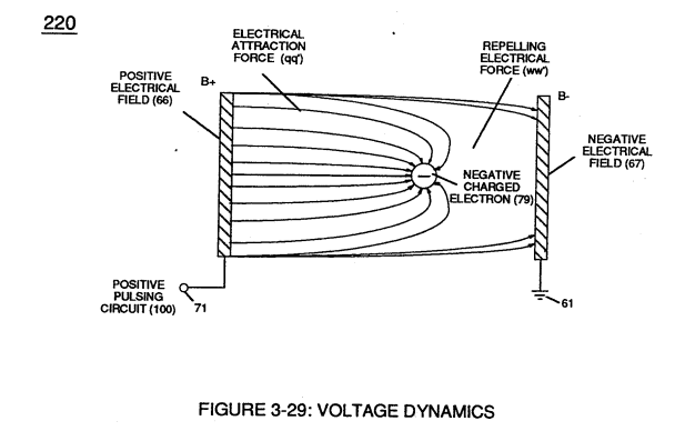
Placement of a pulse voltage potential (65) across Excitor plates (E1/E2) (voltage zones 66/67) of Figure (3-29) as to Figure (3-26) while inhibiting and preventing electron flow within voltage intensifier circuit (190) of Figure (3-23) causes water molecule (210) of Figur …
-
voltage-plate (E2)
… ge zone 66); while, at the same time, opposite polarity electrical attraction force (RR') causes positive charged hydrogen atoms (77a/b) to migrate in the opposite direction to negative voltage-plate (E2) (negative voltage zone 67) as step-charging voltage-wave (65) increases in voltage amplitude from several millivolts to several hundred volts during each pulse train (65a xxx 65n) which, in applicati …
Resonant Action 3×
-
negative voltage-plate (E2)
Intensified electrical attraction force (TT') causes dislodged negative charged electrons (92) to migrate to positive voltage-plate (E1) while electrical attraction force (UU') causes positive charged atom nucleus (94) to travel toward negative voltage-plate (E2).
-
voltage zones (E1/E2)
In terms of Longevity, voltage zones (E1/E2) are composed of or made of stainless steel T304 material which is chemically inert to hydrogen, oxygen, and ambient air gases (dissolved gases in water) being liberated from water bath (68) during voltage stimulation (65).
-
stainless steel voltage plates (E1/E2)
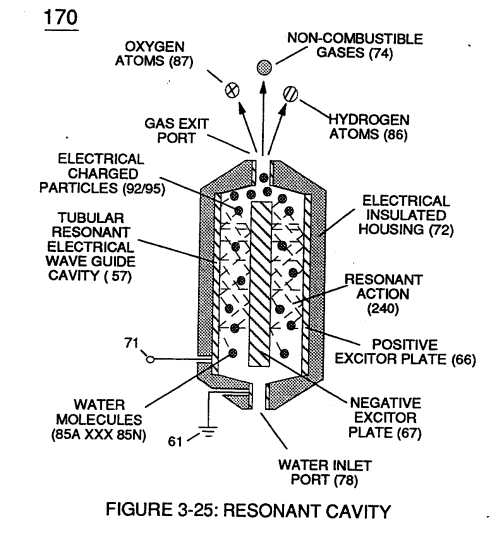
In practice, stainless steel voltage plates (E1/E2) physically forms voltage zones (66/67) regardless of geometric shape or configuration of resonant cavity (170).
Gas Modulator Process 1×
-
voltage zones (E1 / E2)
Inherently, the utilization of the Electrical Polarization Process (160) of Figure (3-26) in conjunction with the use of chemically inert stainless steel (T304 material) voltage zones (E1 / E2) submerged in natural water (68) sustains and maintains gas mixing ratio (88) by simply preventing the consumption of both the hydrogen (86) and oxygen (87) gases by way of not encouraging "electrical …
Impurity Extraction Process 1×
-
applied voltage fields (E1/E2)
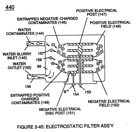
Exposing water contaminates (144a xxx 144n) to applied voltage fields (E1/E2) not only produces electrical charged contaminates (157/158); but, also, kills bacteria that might be present in water bath (68).
Energy Pumping Action 1×
-
Applied voltage fields (66-El/67-E2)
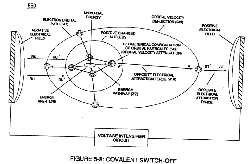
Applied voltage fields (66-El/67-E2) causes and forms both opposite attraction forces (ST - ST') and (RU - RU') across exposed Hydrogen Atom (77) since the negative charged hydrogen electron (1) is attracted and deflected toward stationary positive voltage field (66);
Taper Resonant Capacitor (ERt) 5×
-
Electrical Conducting Plates (E1/E2)
Capacitor (ER) is automatically formed when dielectric liquid of water (Re) is placed between Electrical Conducting Plates (E1/E2) of Figure (1-1) page (1-13) (Memo WFC 420).
-
(E1/E2) of Figure (1-1) page (1-13)
-
Voltage Zones (E1/E2)
Electrical Plates herein called "Excitor" Plates or Voltage Zones (E1/E2) can take-on different configuration of shapes to maximize Dynamic Voltage Potential (600) of Figure (6-3) for different application of usage:
-
Electrical Voltage-Plates (E1/E2)
The dielectric property of water (being 78.54 ohms @ 25° C) permits the storage of '"Electrical Charge" when a potential voltage difference exists between Electrical Voltage-Plates (E1/E2) as to (E9/E10).
-
Electrical Voltage-Plates (E1/E2 - E9/E10)
Capacitance (Cp) of Figure (7-6) as to (690) of Figure (7-8) is determined by the surface area (A) of Electrical Voltage-Plates (E1/E2 - E9/E10), the distance (d) between the Electrical Plates (in inches), and the permittivity (Eo) of the dielectric property of water (85) and, is expressed in the following equation: