(310)
Gas logic circuit
Where it is first named
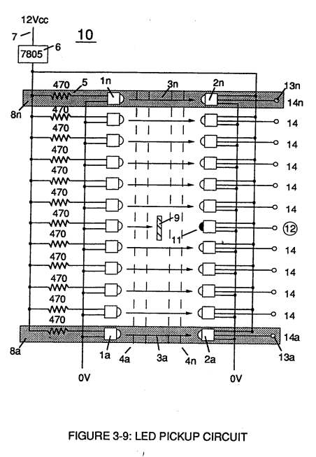
Optical lens (4) of Figure (310) redirects and focuses the transmitted light source (3) of Figure (3-9) (traveling infrared light waves) to the Optoschmitt (2) by passing the light source through a series of concentric lenses (4a xxx 4n) of Figure (3-10) which become progressively smaller from the outer peripheral lens surface (4a) to the inner lens surface (4n).
How it is written
- (310) 2×
Drawings 11
-
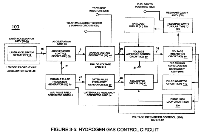
Figure (3-5) · Acceleration Control Circuit (30)
-
Analog Voltage Circuit (40), as shown in Figure (3-5) · Acceleration Control Circuit (30)
-
Figure (3-5) · Acceleration Control Circuit (30)
-
Figure (3-5) · Analog Voltage generator (40)
-
Figure (3-5) · Laser Distributor
-
Carries this number · WFC 422DA - Illustrations
-
2-3 Water Inlet Housing · Water Fuel Injector Illustrations
-
Led Pickup Circuit (10) of Figure (3-9) · Laser Accelerator Assembly
-
The figure it sits on · WFC 422DA - Illustrations
-
3-5 Outer Core Bobbin · Voltage Intensifier Coil Assembly
-
The figure it sits on · Voltage Intensifier Coil Assembly
Where it is named · 2
Laser Accelerator Assembly 1×
-
Optical lens (4) of Figure (310) redirects and focuses the transmitted light source (3) of Figure (3-9) (traveling infrared light waves) to the Optoschmitt (2) by passing the light source through a series of concentric lenses (4a xxx 4n) of Figure (3-10) which become progressively smaller from the outer peripheral lens surface (4a) to the inner lens surface (4n).
Voltage Amplitude Control Circuit (50) 1×
-
Gas logic circuit (310)
Gas logic circuit (310) of Figure (3-5) supplies logic function to Voltage amplitude control circuit (50) to maintain proper gas pressure to gas injector (36) of Figure (3-1) by electronically monitoring achieved gas pressure via pressure sensor (73) of Figure (3-24).