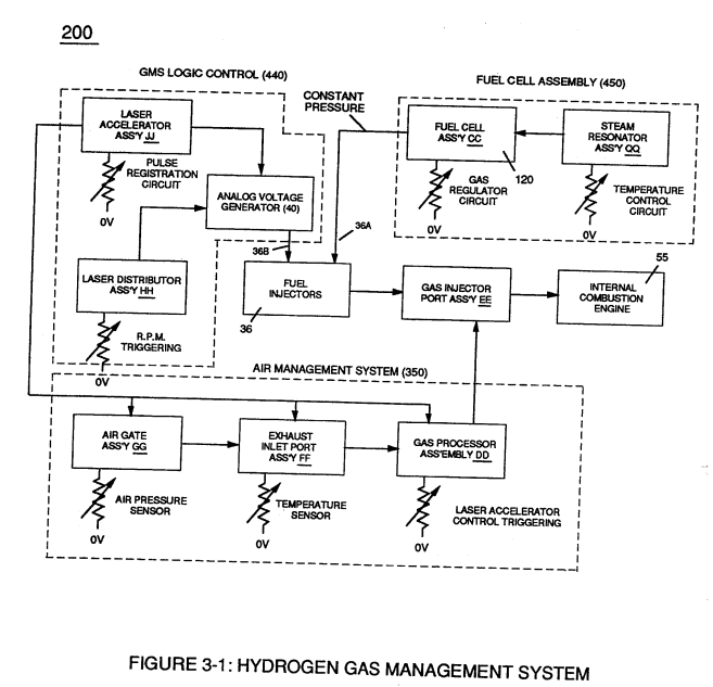
Figure (3-1)
Hydrogen Gas Management System
How it is written
- (3-1) 13×
Drawings 6
-
Captioned as this figure · Laser Accelerator Assembly
-
Figure (3-1) · Voltage Amplitude Control Circuit (50)
-
To further prevent voltage fluctuation during resonant action, Phase Lock Loop technique of Pulse Indicator circuit (110) is utilized during pulsing operations. · Resonant Action
-
Figure (3-1) · Laser Distributor
-
Hydrogen Fuel-Gas Assembly (450) of Figure (3-1) · Operational Parameters
-
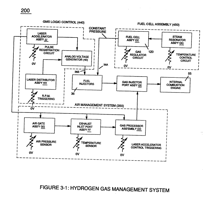
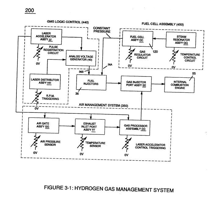
Captioned as this figure · WFC 422DA - Illustrations
On this figure 14
- 10 Led Pickup Circuit
- 12 Logic-Point
- 32 Analog Signal
- 34 Gas Mixing Disc
- 35 Resonant Cavity Zone
- 36 Fuel Injectors
- 40 Fluid-Metering System
- 50 Voltage Amplitude Control Circuit
- 55 Switching Diode
- 200 Hydrogen Gas Control Circuit
- 440 Electrostatic Filter Assembly
- 450 Hydrogen Fuel-Gas Assembly
- GMS Hydrogen Gas Management
- HH Laser Distributor output
Where it is named · 13
Laser Accelerator Assembly 2×
-
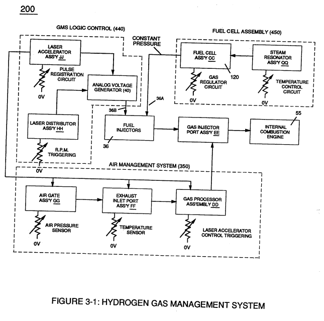
If light emitting diodes (led) (la xxx In) of figure (8) are electrically disconnected from D.C. power supply (6), then Led Pickup Circuit (10) outputs are switch to "low" logic state (l2a xxx 12n) which disallows "low" logic state signal (12), resulting in a "shut-down" condition to Hydrogen Gas Control Circuit (200) of Figure (3-1).
-
Disconnection of power supply (6) to Optoschmitt array (2a xxx 2n) of Figure (3-9) results in a similar "shut down" condition to control circuit (200), as further shown in Figure (3-1).
Voltage Amplitude Control Circuit (50) 4×
-
Second regulator stage (28) simply acts and function as a gas regulator (33) by preventing Fuel Gas production beyond a predetermined gas pressure level (34) of Figure (3-15) during Fuel Cell operations and, as such, maintains constant gas pressure to Fuel Injectors (36) of Figure (3-1) regardless of engine performance (R.P.M. response).
-
Figure (3-1)
Resonant Action 1×
Gas Modulator Process 1×
-
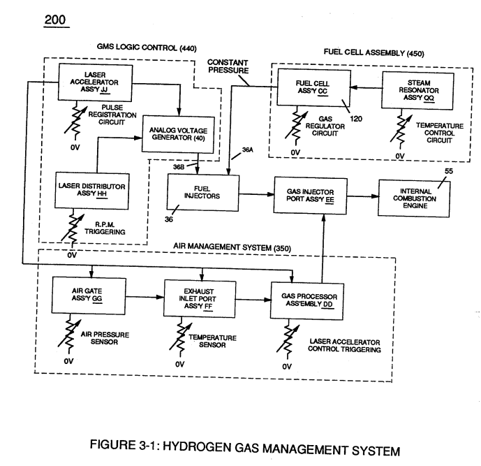
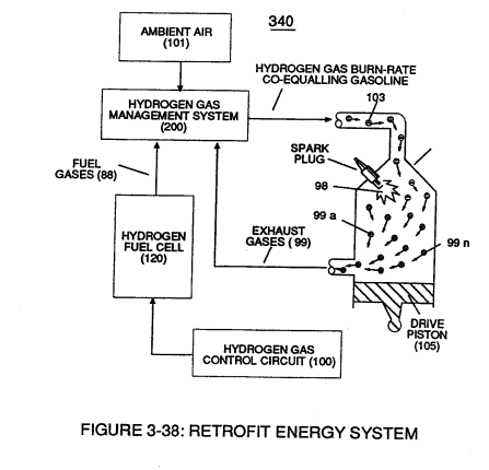
… ultant and on-going Gas Modulator Process (320) of Figure (3-36), now, allows hydrogen fuel cell (120) of Figure (3-24) to be retrofitted to any conventional internal combustion engine (55) of Figure (3-1) without engine change by simply metering the proper amount of exhaust gases (99a xxx 99n) to comply with and co-equaling any type or different fossil-fuel burning levels, as further illustrated in (3 …
Laser Distributor 3×
-
Rotating light-gate triggering circuit assembly (430) sequentially activates Pulse Shaping Generator (440) of Figure (3-4) to produce a constant 50% Duty-cycle Pulse-Train (see Figure 3-16 once again) to Analog voltage Generator (40) of Hydrogen Gas Management System (200) of Figure (3-1) as to Figure (3-5).
-
Figure (3-1)
-
Interlocking Laser Accelerator output {JJ) with Laser Distributor output (HH) of Figure (3-1) causes Fuel-Injectors (36) to be "Tuned" with both Air Management System (350) of Figure (3-2) and Hydrogen Gas Control Circuit (100) of Figure (3-5) to maintain constant Fuel-mixing Ratio (290) of Figure (3-3) during engine performance.
Operational Parameters 2×
-
Coupling and subsequently integrating Hydrogen Gas Management (GMS) system (440) with either Hydrogen Fuel-Gas Assembly (450) of Figure (3-1) or Water Fuel Injector Assembly (10) of Figure (4-1) as to Water Fuel Management (WFMS) System (40) of Figure (4-2), now, sets up a full engineering system-approach on how to use Water as a "New" fuel-source.
-
Hydrogen Fuel-Gas Assembly (450) of Figure (3-1)