(14) · also written as a run, 14a xxx 14n
Response-Time
Also written electrical time-response · Safety Control Circuit · variable time-response · time-response signal · electrostatic force · time variable · toggling-time · nucleus
Where it is first named
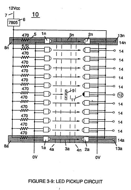
Moving light-gate (9) of figure (3-9) in direct relationship to the physical placement of optical circuits (8a xxx 8n), sets up a time variable (14a xxx 14n) of Figure (3-7) from optical circuits (8x) to another optical circuit (8xx) and/ or (8xxx) or to (8n) since the triggered low logic state (12) of Figure (3-7) and (3-8) moves in direct relationship t …
How it is written
- (14) 17×
- (14/16) 2× with (16) Flame Projection
- (14a xxx ... 12 ... xx14n) 2×
- (14a xxx 14n) 2×
- (14a xxx) 1×
- (14n) 1×
- (14a xxxx ... 12) 1×
- (14a xxx ... 12) 1×
14a xxx 14n is Meyer's shorthand for a run of the same thing: 14a is the first, 14n the last, and the x's stand for however many lie between. Every stage of the run is this one numeral.
Drawings 85
-
I, is the forward current through LED cluster-Array; Vo¢ is volts applied (typically 5 volts). Stanley A. Meyer Page 14 of 28 · WFC 417 — WFC 417
-
Difference of potential between two charges is measured by the work necessary to bring the charges together, and, is given by (Eq 14) · Voltage Performs Work
-
Figure (1-8) · Atomic Interaction to Voltage Stimulation
-
The Positive Electrical Voltage Field (E3) and Negative Electrical Voltage Fields (E4) are triggered "Simultaneously" during the same duty-pulse. · Electron Extraction Process
-
Led Pickup Circuit (10) of Figure (3-9) · Laser Accelerator Assembly
-
Figure (3-12) · Acceleration Control Circuit (30)
-
Figure (3-12) · Acceleration Control Circuit (30)
-
Carries this number · Acceleration Control Circuit (30)
-
Toggling action at full-scale deflection (13a xxx 13n) occurs in the range of (10) kHz or above and thus, allows instant response to driver's acceleration demands. · Acceleration Control Circuit (30)
-
Figure (3-12) · Acceleration Control Circuit (30)
-
Analog Voltage Circuit (40), as shown in Figure (3-5) · Acceleration Control Circuit (30)
-
Carries this number · Analog Voltage generator (40)
-
Figure (3-5) · Analog Voltage generator (40)
-
Whereas, difference of potential between two charges is measured by the work necessary to bring the charges together, and is given by (Eq 14) · Voltage Dynamics
-
Figure (3-5) · Laser Distributor
-
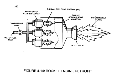
Figure (4-14) · Aviation Application
-
Carries this number · WFC 422DA - Illustrations
-
Carries this number · WFC 422DA - Illustrations
-
Carries this number · WFC 422DA - Illustrations
-
Carries this number · WFC 422DA - Illustrations
-
3-6 Pulsing Core · Voltage Intensifier Coil Assembly
-
3-14 WFC Voltage Ignition Wire · Voltage Intensifier Coil Assembly
-
Carries this number · Electronic Circuit Design
-
Carries this number · Electronic Circuit Design
-
Carries this number · Electronic Circuit Design
-
Carries this number · Electronic Circuit Design
-
Carries this number · Electronic Circuit Design
-
Carries this number · Electronic Circuit Design
-
Carries this number · Electronic Circuit Design
-
Carries this number · Electronic Circuit Design
-
Carries this number · Electronic Circuit Design
-
Carries this number · Electronic Circuit Design
-
Carries this number · Water Fuel Injector (Taper Resonant Cavity Chamber)
-
Carries this number · Water Fuel Injector (Taper Resonant Cavity Chamber)
-
Carries this number · Water Fuel Injector (Taper Resonant Cavity Chamber)
-
(520) of Figure (4-3) · Funneling Effect
-
thereby, attenuating voltage amplitude (voltage intensity) beyond Secondary Coil (53) voltage levels (71), as illustrated in (220) of Figure (18). · Funneling Effect
-
Figure (4-14) · Water Fuel Injection System - Page 3
-
Carries this number · Energy Pumping Action
-
Carries this number · Energy Pumping Action
-
(520) in Figure (5-3) · Resonant Propagation
-
(520) of Figure (5-3) · In Application of Usage
-
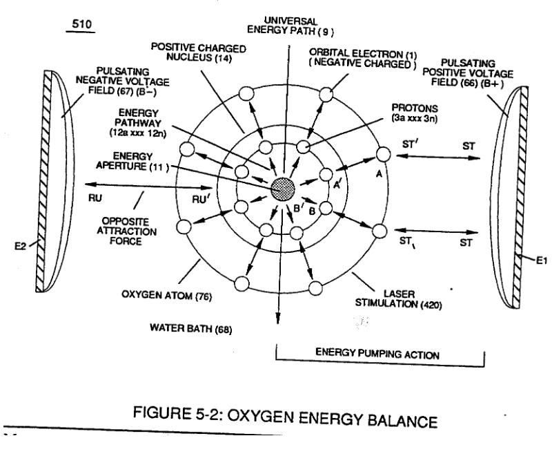
(510) of Figure (5-2) · In Application of Usage
-
(520) of Figure (5-3) · Solar Energy Actuator
-
Carries this number · Illustrations
-
Carries this number · Illustrations
-
Carries this number · Illustrations
-
Hydrogen Fracturing Process (520) of Figure (5-3) · Voltage Intensifier Coil-Assembly
-
(750) of Figure (7-14) · Inductance (FL)
-
(750) of Figure (7-14) · Capacitance (Cd)
-
(547) of Figure (5-9) · Inductance Reactance (Rs - Cd - FL)
-
(750) of Figure (7-14) · Inductance Reactance (Rs - Cd - FL)
-
(760) of Figure (7-15) · Circuit Resistance
-
(547) of Figure (5-9) · Transformer Action
-
Voltage Graph (750) of Figure (7-14) · Electron Bounce Phenomenon
-
Carries this number · WFC 426 - Illustrations
-
(520) of Figure (5-3) · 8-2 - Traveling Voltage Wave-Guides
-
(510) of Figure (5-2) · 8-4 - State Space (Sp)
-
Energy Pumping Action (520) of Figure (5-3) · WFC Development Objectives
-
Figure (5-2) · Propagating Electrical Stress
-
Voltage Performance Graph (750) of Figure (7-14) · Voltage to Amp Differential Ratio
-
Carries this number · The Atom Functioning as an Energy Transporter
-
The figure it sits on · Laser Accelerator Assembly
-
Figure (3-7) · Acceleration Control Circuit (30)
-
Figure (3-5) · Acceleration Control Circuit (30)
-
Figure (3-13) · Acceleration Control Circuit (30)
-
Figure (3-13) · Acceleration Control Circuit (30)
-
Figure (3-5) · Acceleration Control Circuit (30)
-
Figure (3-6) · Voltage Amplitude Control Circuit (50)
-
Figure (3-6) · Cell Driver Circuit (90)
-
The figure it sits on · WFC 422DA - Illustrations
-
The figure it sits on · WFC 422DA - Illustrations
-
The figure it sits on · WFC 422DA - Illustrations
-
The figure it sits on · WFC 422DA - Illustrations
-
3-5 Outer Core Bobbin · Voltage Intensifier Coil Assembly
-
3-7 VIC Amp Inhibitor Coil Ass'y · Voltage Intensifier Coil Assembly
-
3-8 Multi-Coil Spool · Voltage Intensifier Coil Assembly
-
3-13 Flat Seal · Voltage Intensifier Coil Assembly
-
Gas Processor Assembly 2 · Differential Air-Gas Inlet Control
-
Figure (3-6) · Water Fuel Injection System - Page 1
-
Figure (4-9) · Water Fuel Injection System - Page 2
-
(110) of Figure (4-9) · In Application of Usage
-
(110) of Figure (4-9) · Resistance (Rs)
-
Voltage Intensifier Circuit (110) of Figure (4-9) · WFC Exhaust Air Reclaimer
-
Blocking Diode (52) of Figure (4-9) · Propagating Electrical Stress
Where it is named · 27
Acceleration Control Circuit (30) 8×
-
time variable (14a xxx 14n)
Moving light-gate (9) of figure (3-9) in direct relationship to the physical placement of optical circuits (8a xxx 8n), sets up a time variable (14a xxx 14n) of Figure (3-7) from optical circuits (8x) to another optical circuit (8xx) and/ or (8xxx) or to (8n) since the triggered low logic state (12) of Figure (3-7) and (3-8) moves in direct relationship t …
-
response-time (14n)
Deflecting (moving) the light-gate (9) to position (8n) takes longer in response-time (14n) than deflecting the light-gate to position (8x) and/or (8xx) or (8xxxx).
-
electrical time-response (14a xxx 14n)
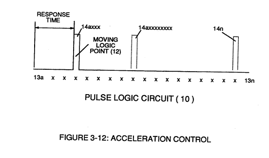
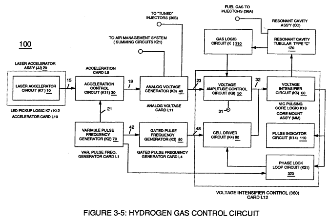
… xxI4n) or signal output (15) of Figure (3-5) is, now, electrically transmitted to Acceleration Control Circuit (30) of Figure (3-5) since Laser Accelerator Assembly (20) of figure (3-10) converts mechanical displacement (9a xxx 9n) to electrical time-response (14a xxx 14n) of Figure (3-7) by linearly moving (forward and/or reverse direction) "low" logic state signal (12) in a array of "high" logic state output signals (13a xxx 13n), as further illustrated in Figure (3- …
-
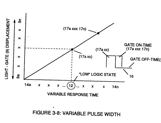
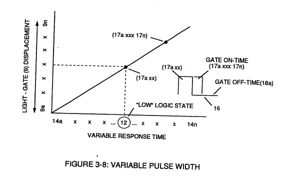
As signal output (15) of figure (4) (14a xxx ... 12 ... xx14n) is being received by acceleration control circuit (30) of Figure (3-5) as to Figure (3-12), circuit (30) converts incoming time-response signal (14a xxx ... 12 ... xx14n) into a variable time-base unipolar pulse (16), as shown in Figure (3-8).
-
time-response signal (14a xxx ... 12 ... xx14n)
As signal output (15) of figure (4) (14a xxx ... 12 ... xx14n) is being received by acceleration control circuit (30) of Figure (3-5) as to Figure (3-12), circuit (30) converts incoming time-response signal (14a xxx ... 12 ... xx14n) into a variable time-base unipolar pulse (16), as shown in Figure (3-8).
-
response-time (14a xxx ... 12)
Circuit (30) electronically and automatically scans output signal-array (14axxx ... 12 ... xx14n) (15) until circuit (30) locates, momentarily registers, and translates response-time (14a xxx ... 12) into a variable unipolar pulse (17/18) of Figure (3-8).
-
variable time-response (14a xxx)
This toggling (flip back) action electronically determines variable time-response (14a xxx) regardless of wherever logic point (12) is being momentarily displaced within circuit array (13a xxx 13n).
-
toggling-time (14a xxxx ... 12)
Circuit (30) continues to increase pulse width (17axxxx) of Figure (3-8) as the monitored (detected by < scanning) toggling-time (14a xxxx ... 12) increases when logic-point (12) moves farther away from start-position (9a) to stop-position (9n), as further shown in Figure (3-13) as to Figure (3-12).
Voltage Amplitude Control Circuit (50) 1×
-
Safety Control Circuit (14)
… s pressure release valve (75) of Figure (3-24) (gas venting 37 of Figure 3-15) expels Fuel gases (88) until gas point (34) is either reached or a delay timing circuit activates Safety Control Circuit (14) of Figure (3-6) which, in turns, switches off or disconnects applied electrical power (28) to Fuel Cell electrical system (400) of Figure (3-6).
Water Fuel Injection System 1×
-
… 420) to cause the resultant highly energized and mass destabilized combustible gas atoms (93a xxx 93n) of Figure (8) to perform Hydrogen Fracturing Process (80) of Figure (7) when electrostatic force (14/16) thermally ignites (kinetic agitation) destabilized water-fuel mixture (93a xxx 93n) under gas compression... …
Water Fuel Injector (Taper Resonant Cavity Chamber) 11×
-
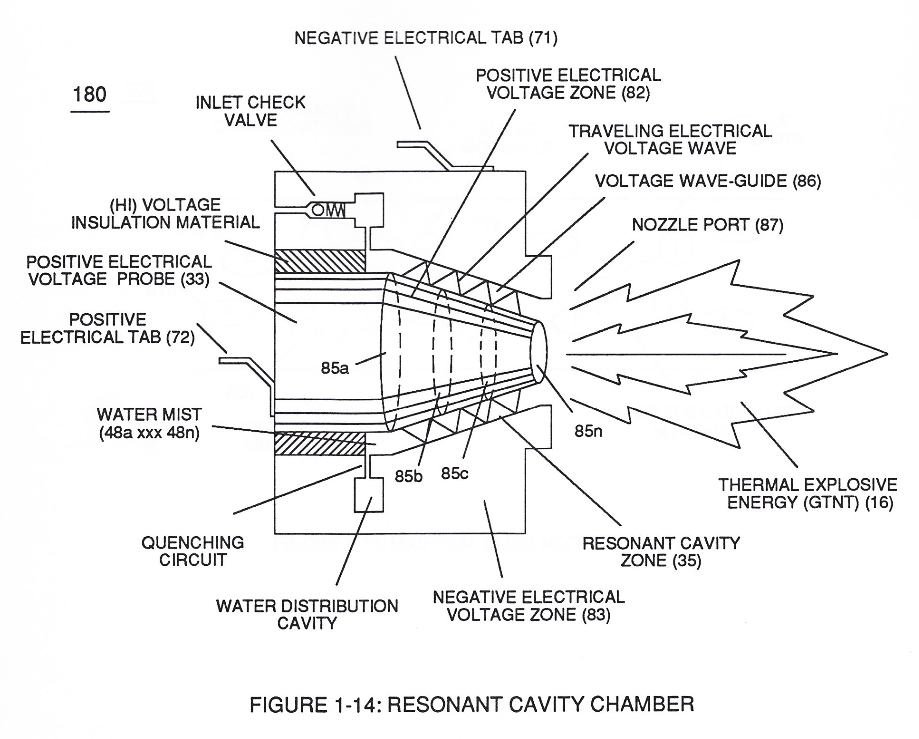
releasing thermal explosive energy (gtnt) via flame projection (16) of Figure (3B) as to Figure (14), Water Fuel Injection System (10) of Figure (1) as to (170) of Figure (13) incorporates and uses Taper Resonant Cavity Chamber (180) of Figure (14) to enhance operational parameters of Hydrogen Fract …
-
… a flame projection (16) of Figure (3B) as to Figure (14), Water Fuel Injection System (10) of Figure (1) as to (170) of Figure (13) incorporates and uses Taper Resonant Cavity Chamber (180) of Figure (14) to enhance operational parameters of Hydrogen Fracturing Process (100) of Figure (6) being stimulated to activation by opposite electrical voltage fields (49/51) of Figure (3B) as to (180) of Figure …
-
… to enhance operational parameters of Hydrogen Fracturing Process (100) of Figure (6) being stimulated to activation by opposite electrical voltage fields (49/51) of Figure (3B) as to (180) of Figure (14).
-
The injected water fuel-droplets (48a xxx 48n), now, surrounds outer surface area of exposed positive probe (33) while entering into Taper Resonant Cavity (180), as illustrated in (70) of Figure (3B) as to Figure (14).
-
Figure (14)
-
… n-flow of water fuel droplets (48a xxx 48n) not only sustains and maintains Hydrogen Fracturing Process (100) of Figure (6) but, also, regulates Thermal Explosive Energy release (16a x 16n) of Figure (14) by attenuating applied voltage amplitude (xxx VL xxx), as graphically shown in Figure (20F) (WFC Memo 420).
-
Thermal Explosive Energy release (16a xxx 16n) of Figure (14)
-
which, in turns, ejects a greater number of electrons while preventing the formation of the water molecule (390) of Figure (41) (WFC Memo 422 DA) during thermal gas-ignition (180) of Figure (14).
-
(180) of Figure (14)
-
This induced voltage phenomenon encourages and therefore prevents resonant pulse frequency (58) from being impaired or altered while being electrically transmitted to Resonant Cavity (180) of Figure (14) via electrical tabs (71) and (72) of Figure (14).
-
This induced voltage phenomenon encourages and therefore prevents resonant pulse frequency (58) from being impaired or altered while being electrically transmitted to Resonant Cavity (180) of Figure (14) via electrical tabs (71) and (72) of Figure (14).
Funneling Effect 4×
-
causing Resonant Cavity Zone (35) to function and perform as a voltage wave-guide (86) of Figure (14) since the gradual decrease in cross-sectional circumference area (85) of Figure (14) is in linear progression ... reducing both voltage surfaces areas (83/84) in parallel space relationship from larger segmental area (85a) to smaller segmental area (85n).
-
causing Resonant Cavity Zone (35) to function and perform as a voltage wave-guide (86) of Figure (14) since the gradual decrease in cross-sectional circumference area (85) of Figure (14) is in linear progression ... reducing both voltage surfaces areas (83/84) in parallel space relationship from larger segmental area (85a) to smaller segmental area (85n).
-
At termination point (85), voltage intensity (VL x Va x Vb x Vc x Vn) is, now, increased to the point to cause Gas Ignition as Combustible Gas Atoms (76, 77a - 77b) which are, then, expelled from Gas Nozzle Port (87) of Figure (14) under dynamic pressure to allow thermal gas expansion (16) ... releasing thermal explosive energy (gtnt) beyond and away from Resonant Cavity Chamber (180), as illustrated in Figure (14).
-
At termination point (85), voltage intensity (VL x Va x Vb x Vc x Vn) is, now, increased to the point to cause Gas Ignition as Combustible Gas Atoms (76, 77a - 77b) which are, then, expelled from Gas Nozzle Port (87) of Figure (14) under dynamic pressure to allow thermal gas expansion (16) ... releasing thermal explosive energy (gtnt) beyond and away from Resonant Cavity Chamber (180), as illustrated in Figure (14).
Water Fuel Injection System - Page 3 1×
-
electrostatic force (14/16)
… to cause the resultant highly energized and mass destabilized combustible gas atoms (93a xxx 93n) of Figure (4-10) to perform Hydrogen Fracturing Process (80) of Figure (4-9) when electrostatic force (14/16) thermally ignites (kinetic agitation) destabilized water-fuel mixture (93a xxx 93n) under gas compression
Energy Pumping Action 1×
-
nucleus (14)
In this phase of application, opposite attraction force (BB') provides a energy transfer path (12) to each respective proton (3a xxx 3n) from energy aperture (11) which is centrally formed during proton grouping ... establishing nucleus (14) of Figure (5-2).