(Rp)
Transformer Magnetic Field
Also written magnetic field · Coupling Inductance · primary electromagnetic coupling field · magnetic coupling field strength · inductance field strength
Where it is first named
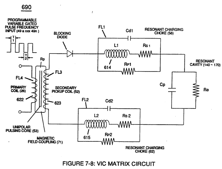
At elevated or higher amplitude voltage levels (xxx Ve xxx Vf xxx Vn), primary electromagnetic coupling field (Rp) of Figure (7-8) transmitted by way of Inductance Pulsing-Core (190) of Figure (3-23) as to VIC Coil Assembly (580) of Figure (6-1) enters into and passes through both Inductors (L1/L2) simultaneously …
How it is written
- (Rp) 13×
- (Rp/71) 1× with (71) Magnetic Field Coupling
Drawings 23
-
The figure it sits on · VIC Matrix Circuit
-
(700) of Figure (7-9) · Instant Explosion of Water
-
(T2) of Figure (7-8) · Instant Explosion of Water
-
Figure (7-8) · Resistance (Rs)
-
(690) of Figure (7-8) · Resistance (Rs)
-
(690) of Figure (7-8) · Inductance (FL)
-
(690) of Figure (7-8) · Capacitance (Cd)
-
(690) of Figure (7-8) · Inductance Reactance (Rs - Cd - FL)
-
"Electron Bounce" phenomenon (700) of Figure (7-9) · Inductance Reactance (Rs - Cd - FL)
-
Figure (7-8) · Inductance Reactance (Rs - Cd - FL)
-
(690) of Figure (7-8) · Taper Resonant Capacitor (ERt)
-
690 of Figure 7-8 · Circuit Resistance
-
"Electron Clustering" (Grouping/collecting negative charged particles at a given point) (700) of Figure (7-9) · Transformer Action
-
(52) of Figure (7-8) · Electron Bounce Phenomenon
-
(700) of Figure (7-9) · Electron Bounce Phenomenon
-
(690) of Figure (7-8) · 8-2 - Traveling Voltage Wave-Guides
-
(631) of Figure (7-9) · 8-3 - Electrical Voltage-Pulse Wave-Transmission
-
(52) of Figure (7-8) · 8-3 - Electrical Voltage-Pulse Wave-Transmission
-
(Cp) of Figure (7-8) · 8-4 - State Space (Sp)
-
(690) of Figure (7-8) · 8-6 - VIC Voltage Sync-Pulse Circuit
-
(Cp) of (7-8) · 8-6 - VIC Voltage Sync-Pulse Circuit
-
(690) of Figure (7-8) · Propagating Electrical Stress
-
The figure it sits on · WFC 429 - Illustrations
Where it is named · 14
Inductance Reactance (Rs - Cd - FL) 3×
-
primary electromagnetic coupling field (Rp)
At elevated or higher amplitude voltage levels (xxx Ve xxx Vf xxx Vn), primary electromagnetic coupling field (Rp) of Figure (7-8) transmitted by way of Inductance Pulsing-Core (190) of Figure (3-23) as to VIC Coil Assembly (580) of Figure (6-1) enters into and passes through both Inductors (L1/L2) simultaneously …
-
(Rp) of Figure (7-8)
-
Electron Inhibiting Effect (631) in direct relationship to Voltage Enhancement Effect (528) is accomplished since stainless steel 430F/FR wire-material is "Electromagnetic Inductive" to incoming electromagnetic flux-lines (71a xxx 71n) (Rp) without (s/s) inductor-wire-coil (L1/L2) becoming permanently magnetized
Circuit Resistance 3×
-
inductance field strength (Rp)
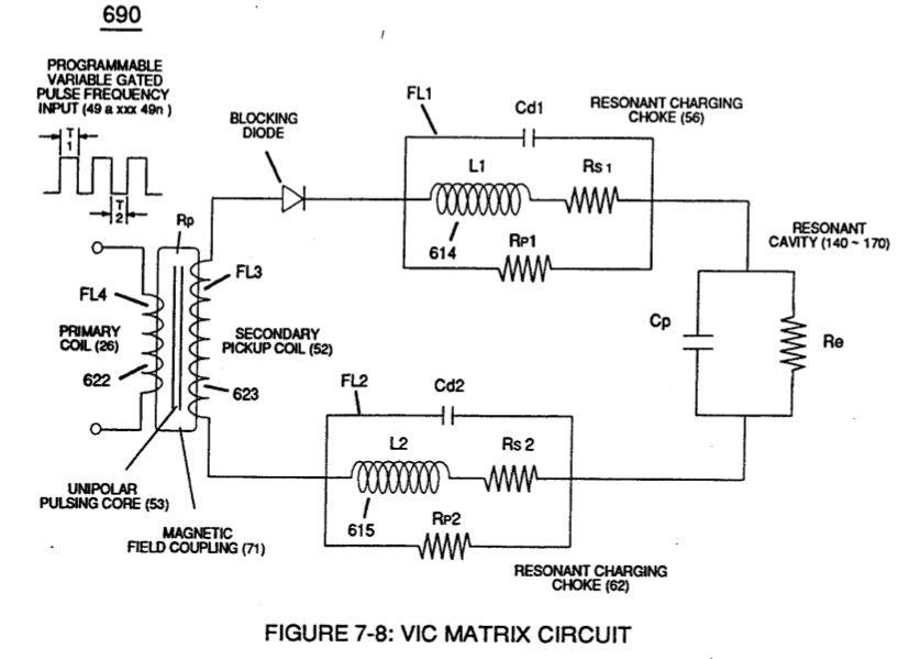
(Rl) is the resistive value of Secondary Pickup Coil (52) of Figure (7-8) plus Magnetic Field strength of primary coupling field (71) in direct relationship to inductance field strength (Rp) which is determined by the number of turns of wire that make up secondary coil-wrap (52),
-
(Z2) is determined by inductance field strength (FL1) and resistive value (RS1) (typically 11.6 KQ) of stainless steel (s/s) wire-coil (56) (LI) when being exposed to external magnetic coupling field strength (Rp),
-
magnetic coupling field strength (Rp)
(Z3) is determined by inductance field strength (FL2) and resistive value (RS2) (typically 11.6KQ) of stainless steel (sls) wire-coil (62) (L2) when being exposed to the same external magnetic coupling field strength (Rp)
Transformer Action 3×
-
Coupling Inductance (Rp)
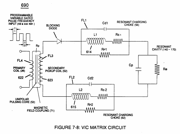
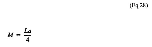
(La) is the total inductance of Primary coil (26) and Secondary coil (52) with fields aiding Coupling Inductance (Rp) between the Primary coil (26) and Secondary Coil (52) is further extrapolated in the following equation:
-
(L1) and (L2) are the inductances of each individual choke coil (56)(62) in series with Secondary Coil (52) Electrical Voltage Potential (700) of Figure (7-9) and being exposed to the same Voltage Transformer (26 - 53 - 52) magnetic field (Rp) with aiding fields,
-
Transformer Magnetic Field (Rp)
(M) is the mutual inductance of choke coils (L1/L2) since Transformer Magnetic Field (Rp) is the excitation External Magnetic Field (Rp1/Rp2) by way of Unipolar Pulsing Core (53).
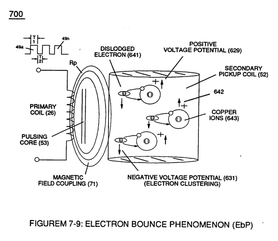

Electron Bounce Phenomenon 4×
-
High Voltage Potential of Difference (Vo - Vn) (SS' - 617 -RR') is accomplished when magnetic flux lines of force (71a xx 71n) (Rp) emanating away from closed-loop magnetic pulsing core (53) of Figure (190) penetrates Inductance coil-windings (52 - 56 - 62) simultaneously during each and every pulse on-time (T1a xxx T1n) as progr …
-
Coupling Inductance (Rp)
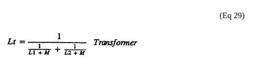
Coupling Inductance (Rp) between the Primary coil (26) and Secondary Coil (52) is further extrapolated in the following equation: Where, (Lt) is the total inductance, (L1) and L2) are the inductance of each individual transformer coils (26)(52), (M) is the mutual inductance of each transformer coil (26/52) being in parallel relationship with fields aiding.
-
magnetic field (Rp)
… ch individual choke coil (56)(62) in series with Secondary Coil (52) Electrical Voltage Potential (700) of Figure (7-9) and being exposed to the same Voltage Transformer (26 - 53 - 52) magnetic field (Rp) with aiding fields, (M) is the mutual inductance of choke coils (L1/L2) since Transformer Magnetic Field (Rp) is the excitation External Magnetic Field (Rp1/Rp2) by way of Unipolar Pulsing Core (53).
-
Transformer Magnetic Field (Rp)
… ure (7-9) and being exposed to the same Voltage Transformer (26 - 53 - 52) magnetic field (Rp) with aiding fields, (M) is the mutual inductance of choke coils (L1/L2) since Transformer Magnetic Field (Rp) is the excitation External Magnetic Field (Rp1/Rp2) by way of Unipolar Pulsing Core (53).
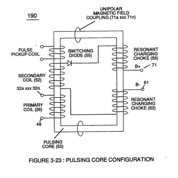
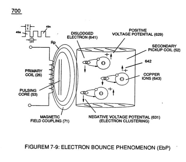
8-3 - Electrical Voltage-Pulse Wave-Transmission 1×
-
… Effect" (631) of Figure (7-9) produces a "Negative Electrical Voltage Intensity (67) in equal magnitude to the "Positive Electrical Voltage Intensity (66) during each/repetitious magnetic pulse-cycle (Rp/71). Remember, Secondary Voltage pickup coil (52) of Figure (7-8) displaces and separates Resonant Charging Chokes (56/62) on opposite end of said Secondary Pickup Coil (52).