(1040)
Differential Voltage Wave-guide
Also written Differential Voltage Wave-Guild
Where it is first named
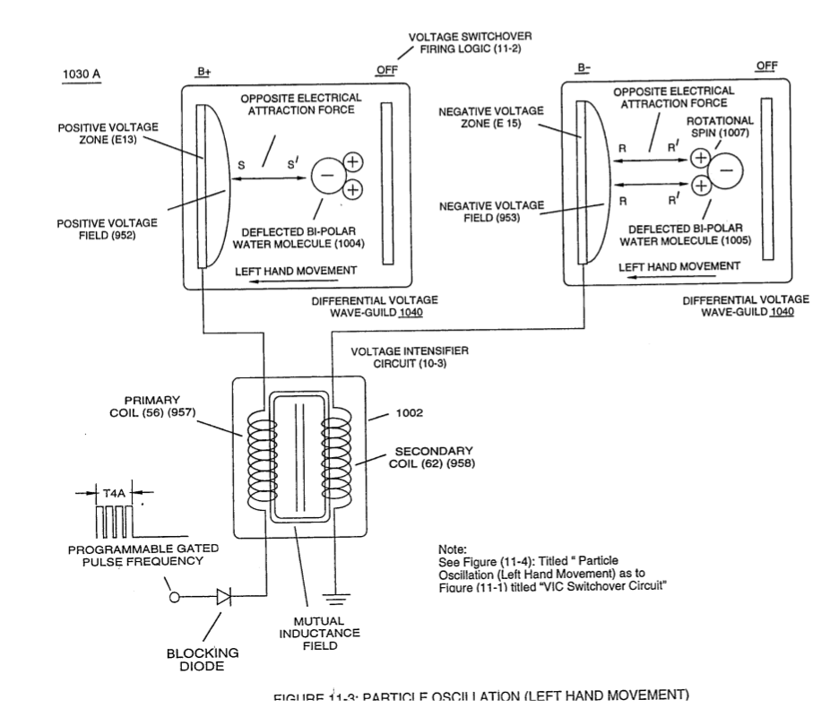
Pairing together positive voltage zone (E13/952) with negative voltage zone (E16/956) and doing the same with voltage-surfaces (E14/953) to (E15/954) as so graphically shown in (1O1O) of Figure (11-1) and each having an longitudinal axis of identical length, now, individually forms what is called hereinafter a "Differential Voltage Wave-guide" (1040)
How it is written
- (1040) 5×
Drawings 6
-
dual unipolar voltage pulse circuit (1010) of Figure (11-1) · Voltage Flexing Process
-
(1030) of figure (11-3) · Voltage Flexing Process
-
Differential Voltage Wave-Guild (1040B) · Electrical Crossover Switching Circuit
-
Carries this number · WFC 430 - Illustrations
-
gated pulse-voltage waveform (1020) of Figure (11-2) · Voltage Flexing Process
-
The figure it sits on · VIC Switchover Circuit
Where it is named · 5
VIC Switchover Circuit 5×
-
Differential Voltage Wave-guide (1040)
Pairing together positive voltage zone (E13/952) with negative voltage zone (E16/956) and doing the same with voltage-surfaces (E14/953) to (E15/954) as so graphically shown in (1O1O) of Figure (11-1) and each having an longitudinal axis of identical length, now, individually forms what is called hereinafter a "Differential Voltage Wave-guide" (1040)
-
Differential Voltage Wave-Guide (1040)
In like manner as to linear cylindrical resonant cavity (730) of Figure (7-12), the Differential Voltage Wave-Guide (1040) of (1010) of Figure (11-1) as to Figure (11-6) is constructed in such a way as to allow a smaller tube to be placed inside a much larger tube having space relationship to allow water to pass there between, as so pictorially shown in (170) of Figure (3-25).
-
… ositive or negative in electrical polarity, to be electrically transmitted and linearly displaced along the longitudinal axis of the inner side walls adjacent to water bath (68), as so illustrated in (1040) of Figure (11-4).
-
Differential Voltage Wave-Guild (1040)
Varying the gated pulse-width (T4A f T4B), attenuating voltage amplitude (xxx Vn), and the Switchover pulse frequency rate (Sopr), collectively determines the rate by which the water temperature rises as the water medium (68) travels through the Differential Voltage Wave-Guild (1040), as so illustrated in (1060) of Figure (11-2) as to (1040) of Figure (11-6).
-
Varying the gated pulse-width (T4A f T4B), attenuating voltage amplitude (xxx Vn), and the Switchover pulse frequency rate (Sopr), collectively determines the rate by which the water temperature rises as the water medium (68) travels through the Differential Voltage Wave-Guild (1040), as so illustrated in (1060) of Figure (11-2) as to (1040) of Figure (11-6).