(1010)
Voltage Rippling Effect
Also written VIC Switchover Circuit · dual unipolar voltage pulse circuit · Voltage Wave burst
Where it is first named
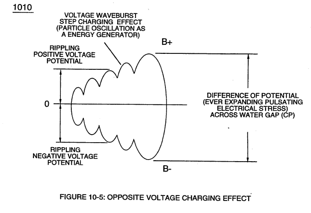
Opposite polarity Voltage Wave burst (1010) of Figure (10-5) as to Dynamic Voltage Stimulation (770B) of Figure (8-1) is simply produced when Programmable Variable Pulse-Width Pulse-Train Waveform (49a xxx 49n) is allowed to be electrically tr …
How it is written
- (1010) 11×
Drawings 3
-
of Figure (10-5) · Voltage to Amp Differential Ratio
-
Carries this number · WFC 429 - Illustrations
-
dual unipolar voltage pulse circuit (1010) of Figure (11-1) · Voltage Flexing Process
Where it is named · 11
Voltage to Amp Differential Ratio 4×
-
Voltage Wave burst (1010)
Opposite polarity Voltage Wave burst (1010) of Figure (10-5) as to Dynamic Voltage Stimulation (770B) of Figure (8-1) is simply produced when Programmable Variable Pulse-Width Pulse-Train Waveform (49a xxx 49n) is allowed to be electrically tr …
-
Voltage Rippling Effect (1010)
Voltage Rippling Effect (1010) of Figure (10-5)
-
Voltage Rippling Effect (1010)
… f Equilibrium" and returning back to "Stable State of Equilibrium" during-pulse off-time (T2) for repeated "Snapping Action" (Rubberbanding effect) in accordance with bi-polar Voltage Rippling Effect (1010) of Figure (10-5), as so illustrated in (280) of Figure (3-35).
Voltage Flexing Process 2×
-
dual unipolar voltage pulse circuit (1010)
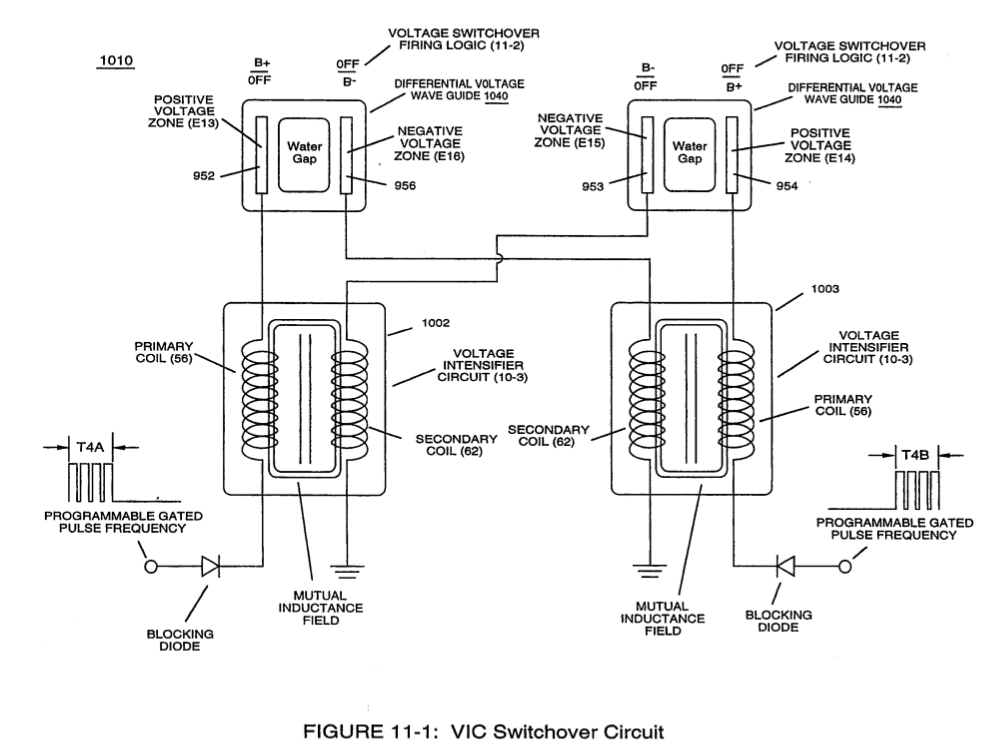
In order to accomplish this task, dual unipolar voltage pulse circuit (1010) of Figure (11-1) is, now, utilized to deflect (Physical Movement) the bipolar electrically charged water molecule (210) of Figure (3-46) while undergoing and experiencing both physical and electrical stress, simultaneously
-
dual unipolar voltage pulse circuit (1010)
dual unipolar voltage pulse circuit (1010) of Figure (11-1)
VIC Switchover Circuit 5×
-
VIC Switchover Circuit (1010)
VIC Switchover Circuit (1010) of Figure (11-1) is utilized to bring about Voltage Flexing Process (1050) by preventing amp influxing into and away from the separate and periodically spaced (-) voltage zones (E13-EI4 - E15-EI6) of diagram (1030) of Figure (11-3) as to (1010) of Figure (11-1);
-
VIC Switchover Circuit (1010) of Figure (11-1) is utilized to bring about Voltage Flexing Process (1050) by preventing amp influxing into and away from the separate and periodically spaced (-) voltage zones (E13-EI4 - E15-EI6) of diagram (1030) of Figure (11-3) as to (1010) of Figure (11-1);
-
VIC Switchover Circuit (1010)
VIC Switchover Circuit (1010) of Figure (11-1)
-
VIC Switchover Circuit (1010)
Electrically interfacing alternate "Switchover" voltage pulse wave-form (T4A/T4B) to each of both VIC Coil-Array (s) (1002/1003) of Figure (11-3) as schematically depicted, now, forms VIC Switchover Circuit (1010) of Figure (11-1).
-
In like manner as to linear cylindrical resonant cavity (730) of Figure (7-12), the Differential Voltage Wave-Guide (1040) of (1010) of Figure (11-1) as to Figure (11-6) is constructed in such a way as to allow a smaller tube to be placed inside a much larger tube having space relationship to allow water to pass there between, as so pictorially shown in (170) of Figure (3-25).