Figure (11-1)
Figure (11-1)
How it is written
- (11-1) 10×
Drawings 2
-
dual unipolar voltage pulse circuit (1010) of Figure (11-1) · Voltage Flexing Process
-
Beside the passage · Wobbling Effect
On this figure 11
- 952 Stationary Voltage Fields
- 953 Stationary Voltage Fields
- 954 Physical Stress
- 956 Voltage Fields
- 1010 Voltage Rippling Effect
- 1020 Gated Pulse-Voltage Waveform
- 1040 Differential Voltage Wave-guide
- E13 Stationary Positive Voltage Plate
- E14 Stationary Voltage Fields
- E15 Electrical Voltage Fields
- E16 Electrical Voltage Fields
Where it is named · 10
Wobbling Effect 2×
-
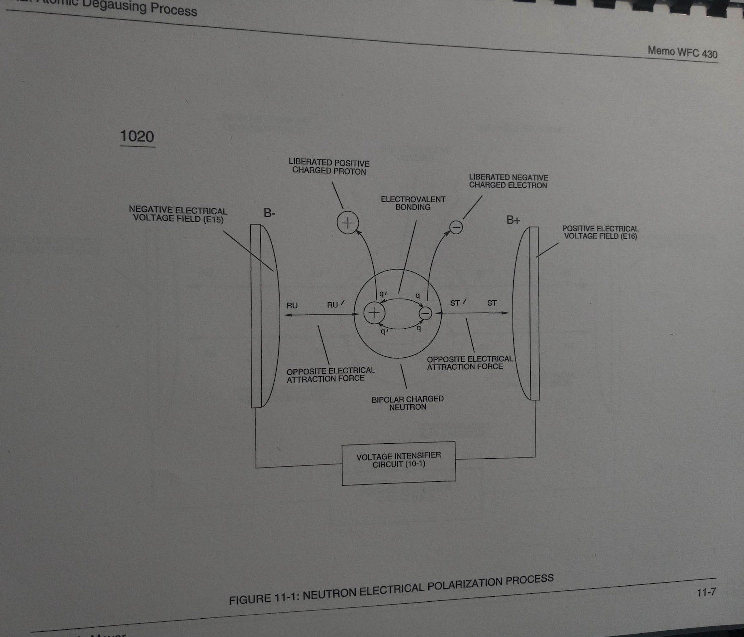
… lectrical charged sub-particles of the atom and the recurring pulsating electrical voltage fields (E15/E16) of opposite electrical polarity of potential (B+/B-), as so illustrated in (1020) of Figure (11-1) titled “Neutron Electrical Polarization Process” as to Figure (10-1) titled “Voltage Intensifier Circuit”.
-
The surplus electromagnetic energy (gamma ray absorption), if any, is simply absorbed into the energy spectrum of the atom when the atom transmutes into another element (s) during the Neutron Electrical Polarization Process, as so illustrated in (1020) of Figure (11-1).
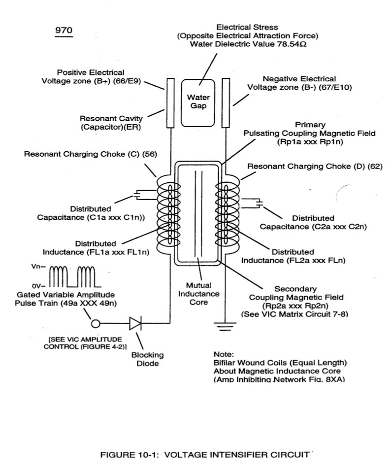
Voltage Flexing Process 2×
-
dual unipolar voltage pulse circuit (1010) of Figure (11-1)
VIC Switchover Circuit 6×
-
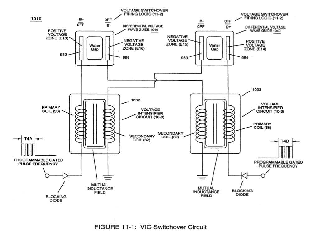
VIC Switchover Circuit (1010) of Figure (11-1)
-
Electrically interfacing alternate "Switchover" voltage pulse wave-form (T4A/T4B) to each of both VIC Coil-Array (s) (1002/1003) of Figure (11-3) as schematically depicted, now, forms VIC Switchover Circuit (1010) of Figure (11-1).
-
Pairing together positive voltage zone (E13/952) with negative voltage zone (E16/956) and doing the same with voltage-surfaces (E14/953) to (E15/954) as so graphically shown in (1O1O) of Figure (11-1) and each having an longitudinal axis of identical length, now, individually forms what is called hereinafter a "Differential Voltage Wave-guide" (1040)
-
In like manner as to linear cylindrical resonant cavity (730) of Figure (7-12), the Differential Voltage Wave-Guide (1040) of (1010) of Figure (11-1) as to Figure (11-6) is constructed in such a way as to allow a smaller tube to be placed inside a much larger tube having space relationship to allow water to pass there between, as so pictorially shown in (170) of Figure (3-25).