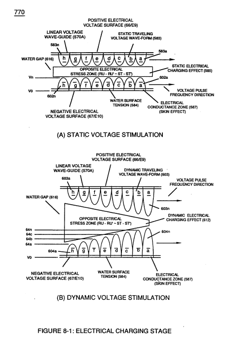
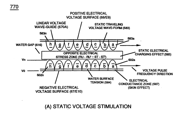
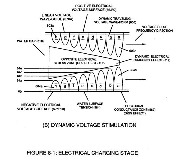
(602) · also written as a run, 602a xxx 602n
Voltage Pulse Train
Also written Unipolar Voltage Pulse Train · Traveling Electrical Voltage Wave-Guide · Voltage Sync-Pulse Gated Frequency · Unipolar Voltage Pulse Wave · opposite Voltage Pulse Wave · Electrical Voltage-Wave · Unipolar Pulse Train · Pulse Wave-Form and 1 more
Where it is first named
… n (Eq 21) and the Voltage Coefficient of the stainless steel (s/s) material fanning voltage surfaces (E9/E10), now, allows the establishment and performance of Traveling Electrical Voltage Wave-Guide (583/602) since electrical conductance zone (587) between electrical surface (S) (E9/E10) and the dielectric surface tension of water (584) acts and performs as a electrical conductor (Skin Effect)
How it is written
- (583/602) 4× with (583) Voltage Pulse Train
- (583/602a xxx 583/602n) 3× with (583) Voltage Pulse Train
- (583 - 602) 2× with (583) Voltage Pulse Train
- (66- 583/67-602) 1× with (66) Positive Voltage Potential, (583) Voltage Pulse Train, (67) Opposite Polarity
- (66-583 - 67-602) 1× with (66) Positive Voltage Potential, (583) Voltage Pulse Train, (67) Opposite Polarity
- (67 - 602a xxx 602n) 1×
- (583/602a xxx 583/602) 1× with (583) Voltage Pulse Train
- (583a/602a-583b/602b - 583n/602n) 1× with (583) Voltage Pulse Train
602a xxx 602n is Meyer's shorthand for a run of the same thing: 602a is the first, 602n the last, and the x's stand for however many lie between. Every stage of the run is this one numeral. A pair before the letters, 583/602a, is a run of two things that go together, one of each per stage.
Drawings 39
-
(840) of Figure (8-10) · 8-6 - VIC Voltage Sync-Pulse Circuit
-
Carries this number · WFC 427 Illustrations
-
Carries this number · WFC 427 Illustrations
-
(650) of Figure (7-4) · Amp Inhibiting Circuit Vs Voltage Enhancement
-
(700) of Figure (7-9) · Instant Explosion of Water
-
(650) of Figure (7-4) · Resistance (Rs)
-
The figure it sits on · Inductance (FL)
-
(650) of Figure (7-4) · Inductance (FL)
-
(650) of Figure (7-4) · Capacitance (Cd)
-
"Electron Bounce" phenomenon (700) of Figure (7-9) · Inductance Reactance (Rs - Cd - FL)
-
"Voltage Deflection" of Figure (7-4) · Capacitance Reactance
-
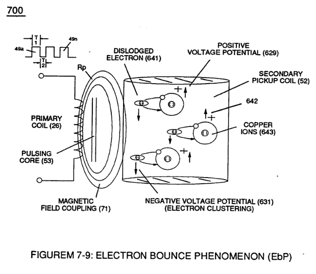
"Electron Clustering" (Grouping/collecting negative charged particles at a given point) (700) of Figure (7-9) · Transformer Action
-
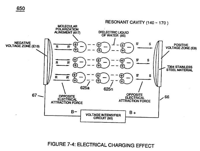
Opposite Electrical Attraction Force (SS' ~ 617 ~ RR' - T3 - SS' ~ 617 - RR') of Figure (7-4) · Electron Bounce Phenomenon
-
(700) of Figure (7-9) · Electron Bounce Phenomenon
-
The figure it sits on · WFC 426 - Illustrations
-
(780A) Figure (8-2) · 8-2 - Traveling Voltage Wave-Guides
-
The figure it sits on · 8-2 - Traveling Voltage Wave-Guides
-
(770) of Figure(8-1) · 8-2 - Traveling Voltage Wave-Guides
-
Figure (8-2) · 8-2 - Traveling Voltage Wave-Guides
-
(770) of Figure (8-1) · 8-3 - Electrical Voltage-Pulse Wave-Transmission
-
(631) of Figure (7-9) · 8-3 - Electrical Voltage-Pulse Wave-Transmission
-
(770 A) of Figure (8-1) · 8-4 - State Space (Sp)
-
(650) of Figure (7-4) · 8-4 - State Space (Sp)
-
(770 B) of Figure (8-1) · 8-4 - State Space (Sp)
-
(780 B) of Figure (8-2) · 8-4 - State Space (Sp)
-
(780 A/B/C) of Figure (8-2) · 8-4 - State Space (Sp)
-
(585) of Figure (8-1) · 8-4 - State Space (Sp)
-
(770A) of Figure (8-1) · 8-5 - Energy Vectoring (Ev)
-
Clipped Voltage Wave-form (780C) of Figure (8-2) · 8-5 - Energy Vectoring (Ev)
-
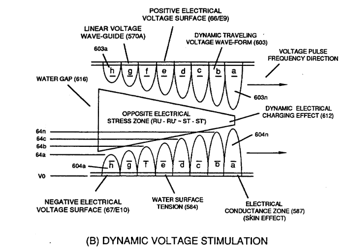
(612) of Figure (8-1) · 8-5 - Energy Vectoring (Ev)
-
The figure it sits on · 8-6 - VIC Voltage Sync-Pulse Circuit
-
(650) of Figure (7-4) · 8-6 - VIC Voltage Sync-Pulse Circuit
-
The figure it sits on · WFC 427 Illustrations
-
"Voltage Tickling of State Space" (770A) of Figure (8-1) · WFC Exhaust Air Reclaimer
-
"Voltage Tickling of State Space" (770B) of Figure (8-1) · WFC Exhaust Air Reclaimer
-
The figure it sits on · Propagating Electrical Stress
-
Dynamic Electrical Charging Effect (612) of Figure (8-1) · Propagating Electrical Stress
-
The figure it sits on · Quartz Tube Configuration & Operational Parameters
-
... establishing variable Dynamic Electrical Charging Effect (612). · Quartz Tube Configuration & Operational Parameters
Where it is named · 14
8-2 - Traveling Voltage Wave-Guides 1×
-
Traveling Electrical Voltage Wave-Guide (583/602)
… n (Eq 21) and the Voltage Coefficient of the stainless steel (s/s) material fanning voltage surfaces (E9/E10), now, allows the establishment and performance of Traveling Electrical Voltage Wave-Guide (583/602) since electrical conductance zone (587) between electrical surface (S) (E9/E10) and the dielectric surface tension of water (584) acts and performs as a electrical conductor (Skin Effect)
8-3 - Electrical Voltage-Pulse Wave-Transmission 1×
-
Voltage Pulse Train (67 - 602a xxx 602n)
Opposite negative Voltage Pulse Train (67 - 602a xxx 602n) is similarly formed since "Electron Clustering Effect" (631) of Figure (7-9) produces a "Negative Electrical Voltage Intensity (67) in equal magnitude to the "Positive Electrical Voltage Intensity (66) during each/repetitious magnetic pulse-cycle (Rp/71). …
8-4 - State Space (Sp) 4×
-
Electrical Voltage-Wave (66-583 - 67-602)
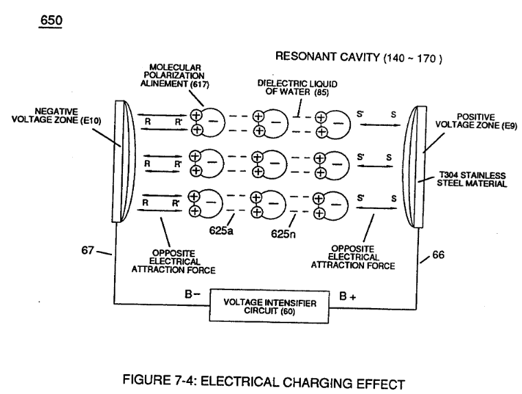
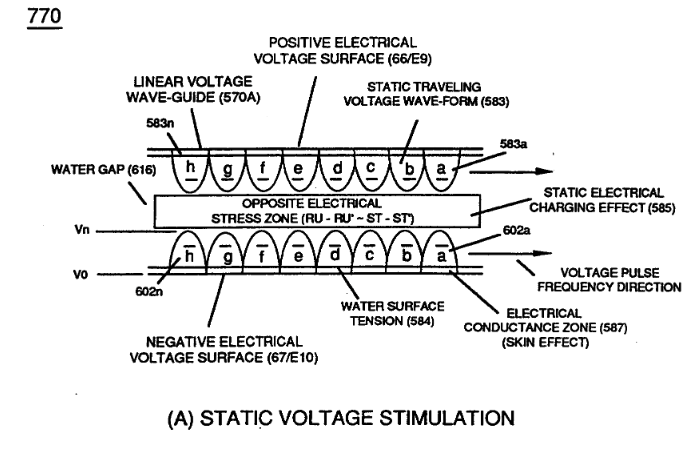
During the electrical-formation (66- Vpa/Vpb - 67- Vpa/Vpb) of each opposite Electrical Voltage-Wave (66-583 - 67-602), opposite electrical attraction force (RR' - SS') of Figure (7-4) is produced across water cap (Cp) of Figure (7-8) which, now, sets up and defines the conditions of “State Space," as illustrated in (770 A/B) of Figure (8-1) as to (650) of Figure (7-4).
-
Unipolar Voltage Pulse Wave (583/602)
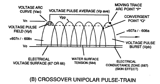
… related to the applied Voltage Amplitude Burst-Time (Vpa - Vn -Vpb) as to the Voltage Burst-Frequency (49a xxx 49n) as to Voltage Peak Excursion Point "P" at the height of Unipolar Voltage Pulse Wave (583/602) which, in turns, determines maximum Voltage Peak-Potential (Vpp) at any given time during each Voltage Pulsing Cycle (Vpa/Vpb).
-
Pulse Wave-Form (66- 583/67-602)
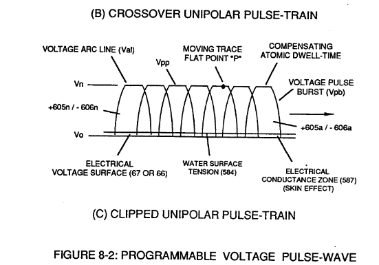
Electrical Attraction Force intensity (RR' - SS' as to RU/RU' - ST/ST' as to 550 of Figure 5-8) at Peak Voltage Potential (Vpp) is either increasing or decreasing or remaining constant as to Voltage Peak Excursion Point "P" trace-position which scans the exact Pulse Wave-Form (66- 583/67-602) being produced, as illustrated in (780B) of Figure (8-2).
-
Voltage Pulse Train (583/602a xxx 583/602n)
Equalizing Voltage Pulse-Scan (Bps) from start of one Voltage Pulse-Field (Vpf) to the start of next Voltage Pulse-Field (Vpfa + Vpfb + Vpfc + Vpfn) is determined by the total average of the number of applied Voltage-Pulses (Vp ave.) making up opposite Voltage Pulse Train (583/602a xxx 583/602n) in synchronous movement.
8-5 - Energy Vectoring (Ev) 3×
-
opposite Voltage Pulse Wave (583 - 602)
… which combined together (Vpf + Vpb) Electrical Stress (Es) variances corresponds to the Voltage Pulse Shape of each synchronized opposite Voltage Pulse Wave (583 - 602) of (770A) of Figure (8-1) being produced during applied Voltage Pulse Operation (49a xxx 49n);
-
Static State Space (Sss) is the electrical condition by which Electrical Attraction Force (RR' - SS' as to RU/RU' - ST/ST') is being held constant once Voltage Pulse Burst Vpb) occurs during Voltage Pulsing Operation (Vpwf) ... forming synchronized Clipped Voltage Wave-form (780C) of Figure (8-2) in like manner to voltage sync-pulse (583 - 602).
-
Unipolar Voltage Pulse Train (583/602a xxx 583/602)
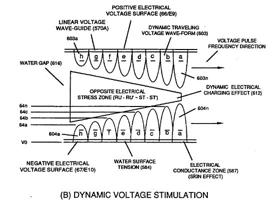
In the area of Voltage Sync-Wave (+/-) propagation, Unipolar Voltage Pulse Train (583/602a xxx 583/602) of (770A) of Figure (8-1), clipped Voltage Pulse Train (605/606a xxx 605/606n) of Figure (780C) of Figure (8-2), and Crossover Unipolar Pulse Train (607/608a xxx 607/608n) brings-on Static Voltage St …
8-6 - VIC Voltage Sync-Pulse Circuit 1×
-
Voltage Sync-Pulse Gated Frequency (583/602a xxx 583/602n)
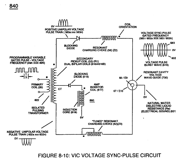
Voltage Sync-Pulse Gated Frequency (583/602a xxx 583/602n) (603/604a xxx 603/604n) of Figure (8-1) as to (605/606a xxx 605/606n) (607/608a xxx 607/608n) (609/611a xxx 609/611n) of Figure (8-2)
Quartz Tube Configuration & Operational Parameters 4×
-
… p "Voltage Tickling of State Space" which takes the hydrogen atom (s) from "Quiescent State" (Qs) to "Active State" (As) and then back again to "Quiescent State" (Qs) once applied unipolar pulse-wave (583/602) goes through Voltage Pulsing Cycle (Vpwf) from "Ground State" (Gs) to Voltage Peak potential (Vpp) (780) of Figure (8-2A) and then returns to "Ground State" (Gs) for continued repetitive Voltage-Puls …
-
Voltage-Pulsing (583/602a xxx 583/602n)
… s through Voltage Pulsing Cycle (Vpwf) from "Ground State" (Gs) to Voltage Peak potential (Vpp) (780) of Figure (8-2A) and then returns to "Ground State" (Gs) for continued repetitive Voltage-Pulsing (583/602a xxx 583/602n)
-
Unipolar Pulse Train (583a/602a-583b/602b - 583n/602n)
The Electrical Conduction Zone (587) (Skin Effect) between the dielectric gas medium (919) and the Electrical Contact Surface of the inside surface area of the Voltage Wave-Guides (66/67) allows Unipolar Pulse Train (583a/602a-583b/602b - 583n/602n) to travel the entire length of the Voltage Wave Guides that make up Voltage Zones (66/E9 – 67/E10).
-
In both cases, Static Voltage Stimulation (770) of Figure (8-1A) and Dynamic Voltage Stimulation (770) of Figure (8-1B) incorporates the use of Positive Electrical Voltage Potential (B+) (Ell) and Negative Electrical Voltage Potential (B-) (EI2) to form synchronized diametrically opposed Voltage Gate-Pulse (Vgp) (583/602) across Vacuum Gap (Vc)