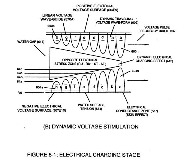
Figure (8-1B)
Figure (8-1B)
How it is written
- (8-1B) 3×
Drawings 2
-
... see Dynamic Voltage Waveform (770) of Figure (8-1), once again. · Voltage to Amp Differential Ratio
-
... establishing variable Dynamic Electrical Charging Effect (612). · Quartz Tube Configuration & Operational Parameters
On this figure 13
- 583 Voltage Pulse Train
- 602 Voltage Pulse Train
- 612 Dynamic Electrical Charging Effect
- 770 Static Voltage Stimulation
- Cp Water Gap
- EI2 —
- Ell —
- RU Electrical Stress
- RU' Electrical Stress
- ST Electrical Stress
- ST' Electrical Stress
- Vgp Opposite Voltage Potential
- Vpf Voltage Pulsing Cycle
Where it is named · 3
Voltage to Amp Differential Ratio 1×
-
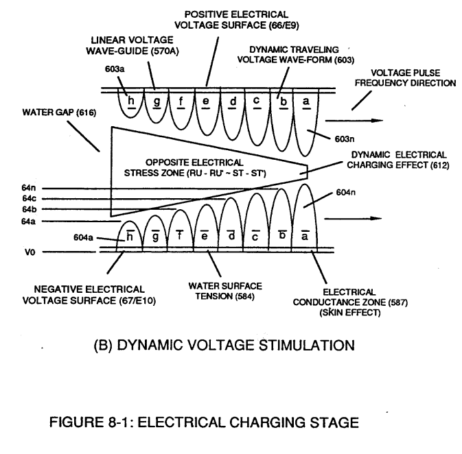
The resultant ever increasing pulsating opposite electrical voltage fields (603/604a xxx 603/604n) of Figure (8-1) having superimposed thereon counter opposing Rippling Voltage-Surfaces (64/B+a xxx 64/B-n) [Dynamic Electrical Charging Effect (612) of Figure (8-1B)], now, set ups, causes, and applies ever increasing (rubberbanding effect) Pulsating Opposite Electrical Stress (RU-RU' - ST-ST') across Water Gap (Cp)
Quartz Tube Configuration & Operational Parameters 2×
-
In both cases, Static Voltage Stimulation (770) of Figure (8-1A) and Dynamic Voltage Stimulation (770) of Figure (8-1B) incorporates the use of Positive Electrical Voltage Potential (B+) (Ell) and Negative Electrical Voltage Potential (B-) (EI2) to form synchronized diametrically opposed Voltage Gate-Pulse (Vgp) (583/602) across Vacuum Gap (Vc)