(12) · also written as a run, 12a xxx 12n
Logic-Point
Also written opposite logic state · low logic state · logic state · logic state signal · energy transfer path · output signal-array · logic function · logic signal and 2 more
Where it is first named
… B+) (13) to on-state (the minimum irradiance that will switch the output low) which switches or triggers the Optoschmitt (2) output to ground state (zero volts) (12).
How it is written
- (12) 15×
- (12a xxx ... 13 ... xxx 12n) 1×
- (14axxx ... 12 ... xx14n) 1×
- (l2a xxx 12n) 1×
12a xxx 12n is Meyer's shorthand for a run of the same thing: 12a is the first, 12n the last, and the x's stand for however many lie between. Every stage of the run is this one numeral.
Drawings 76
-
Stanley A. Meyer Page 12 of 28 · WFC 417 — WFC 417
-
Furthermore, electrical charged ions or particles can move toward stationary voltage fields of opposite polarity, and, is given by Newton's second Law (Eq 12) · Voltage Performs Work
-
Figure (1-12) · Laser Interaction
-
Carries this number · Laser Accelerator Assembly
-
Figure (3-12) · Acceleration Control Circuit (30)
-
Figure (3-7) · Acceleration Control Circuit (30)
-
Figure (3-12) · Acceleration Control Circuit (30)
-
Figure (3-12) · Acceleration Control Circuit (30)
-
Figure (3-6) · Voltage Amplitude Control Circuit (50)
-
Figure (3-6) · Cell Driver Circuit (90)
-
Ions or particle mass having the same or like electrical charges will move away from one another, as illustrated in (220) of Figure (3-29). · Voltage Dynamics
-
reciprocating WFC Fuel-kits can be similar to Car design (340); · Aviation Application
-
Carries this number · WFC 422DA - Illustrations
-
Carries this number · WFC 422DA - Illustrations
-
Carries this number · WFC 422DA - Illustrations
-
Carries this number · Voltage Intensifier Coil Assembly
-
Carries this number · Electronic Circuit Design
-
Carries this number · Electronic Circuit Design
-
Carries this number · Electronic Circuit Design
-
Carries this number · Electronic Circuit Design
-
Carries this number · Electronic Circuit Design
-
Carries this number · Electronic Circuit Design
-
Carries this number · Electronic Circuit Design
-
Carries this number · Electronic Circuit Design
-
Carries this number · Electronic Circuit Design
-
Carries this number · Electronic Circuit Design
-
Carries this number · Electronic Circuit Design
-
Carries this number · Electronic Circuit Design
-
Carries this number · Electronic Circuit Design
-
Carries this number · Electronic Circuit Design
-
Carries this number · Electronic Circuit Design
-
Carries this number · Electronic Circuit Design
-
Carries this number · Electronic Circuit Design
-
Carries this number · Electronic Circuit Design
-
Carries this number · Electronic Circuit Design
-
Carries this number · Electronic Circuit Design
-
Water Fuel Injection System (10) of Figure (1) · Water Fuel Injector (Taper Resonant Cavity Chamber)
-
Carries this number · Water Fuel Injector (Taper Resonant Cavity Chamber)
-
thereby, attenuating voltage amplitude (voltage intensity) beyond Secondary Coil (53) voltage levels (71), as illustrated in (220) of Figure (18). · Funneling Effect
-
Figure (3-6) · Water Fuel Injection System - Page 1
-
Figure (4-12) · Water Fuel Injection System - Page 3
-
Carries this number · Energy Pumping Action
-
(510) of Figure (5-2) · In Application of Usage
-
(970) of Figure (5-12) · Solar Energy Actuator
-
Carries this number · Illustrations
-
Carries this number · Illustrations
-
Traveling Electrical Voltage Wave-forms (730a - b - c) of Figure (7-12) · Electron Bounce Phenomenon
-
Carries this number · Mode of Operability
-
(510) of Figure (5-2) · 8-4 - State Space (Sp)
-
(730C) of Figure (7-12) · 8-7 - Application of Usage
-
Figure (5-2) · Propagating Electrical Stress
-
Carries this number · VIC Switchover Circuit
-
Led Pickup Circuit (10) of Figure (3-9) · Laser Accelerator Assembly
-
The figure it sits on · Laser Accelerator Assembly
-
The figure it sits on · Acceleration Control Circuit (30)
-
Toggling action at full-scale deflection (13a xxx 13n) occurs in the range of (10) kHz or above and thus, allows instant response to driver's acceleration demands. · Acceleration Control Circuit (30)
-
Figure (3-13) · Acceleration Control Circuit (30)
-
Figure (3-13) · Acceleration Control Circuit (30)
-
Figure (3-21) · Voltage Amplitude Control Circuit (50)
-
Figure (3-1) · Voltage Amplitude Control Circuit (50)
-
Figure (3-21) · Voltage Intensifier Circuit (60)
-
The figure it sits on · Voltage Dynamics
-
To further prevent voltage fluctuation during resonant action, Phase Lock Loop technique of Pulse Indicator circuit (110) is utilized during pulsing operations. · Resonant Action
-
The figure it sits on · Gas Processor
-
Figure (3-1) · Laser Distributor
-
Hydrogen Fuel-Gas Assembly (450) of Figure (3-1) · Operational Parameters
-
The figure it sits on · WFC 422DA - Illustrations
-
The figure it sits on · WFC 422DA - Illustrations
-
The figure it sits on · WFC 422DA - Illustrations
-
The figure it sits on · WFC 422DA - Illustrations
-
The figure it sits on · WFC 422DA - Illustrations
-
3-7 VIC Amp Inhibitor Coil Ass'y · Voltage Intensifier Coil Assembly
-
3-8 Multi-Coil Spool · Voltage Intensifier Coil Assembly
-
The figure it sits on · Voltage Intensifier Coil Assembly
-
3-13 Flat Seal · Voltage Intensifier Coil Assembly
-
Gas Processor Assembly 2 · Differential Air-Gas Inlet Control
Where it is named · 18
Laser Accelerator Assembly 6×
-
… B+) (13) to on-state (the minimum irradiance that will switch the output low) which switches or triggers the Optoschmitt (2) output to ground state (zero volts) (12).
-
opposite logic state (12)
Once light-gate (9) blocks and prevents traveling light-beam (3) from reaching the matched Optoschmitt (8xx), the darken Optoschmitt (11) (non-energized) changes output state since the irradiance energy level (3) is reduced to, or below the release point...triggering opposite logic state (12).
-
logic function (12)
As light-gate (9) advances to the next optical circuit (8xxx) a new and separate low-state logic function (12) occurs while the previous optical circuit (8xx) reverts back to high-state logic (13).
-
logic state (12)
Opposite placement of the matched infrared devices (1)(2) prevents bogus or false triggering of "low" logic state (12) during light-gate displacement (9a xxx 9n) of Figure (6)(7) and (8).
-
If light emitting diodes (led) (la xxx In) of figure (8) are electrically disconnected from D.C. power supply (6), then Led Pickup Circuit (10) outputs are switch to "low" logic state (l2a xxx 12n) which disallows "low" logic state signal (12), resulting in a "shut-down" condition to Hydrogen Gas Control Circuit (200) of Figure (3-1).
-
logic state signal (12)
If light emitting diodes (led) (la xxx In) of figure (8) are electrically disconnected from D.C. power supply (6), then Led Pickup Circuit (10) outputs are switch to "low" logic state (l2a xxx 12n) which disallows "low" logic state signal (12), resulting in a "shut-down" condition to Hydrogen Gas Control Circuit (200) of Figure (3-1).
Acceleration Control Circuit (30) 9×
-
low logic state (12)
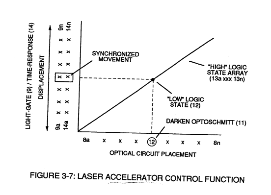
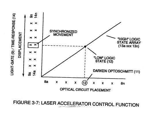
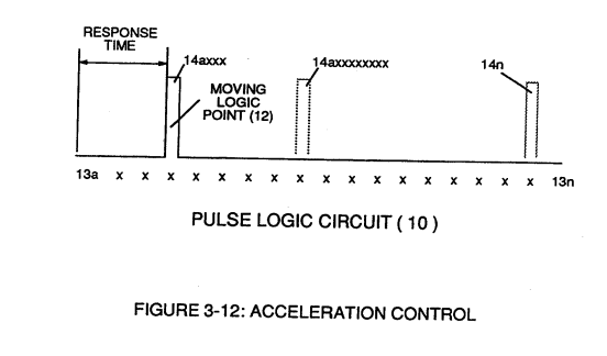
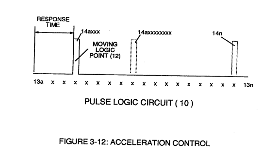
… l circuits (8a xxx 8n), sets up a time variable (14a xxx 14n) of Figure (3-7) from optical circuits (8x) to another optical circuit (8xx) and/ or (8xxx) or to (8n) since the triggered low logic state (12) of Figure (3-7) and (3-8) moves in direct relationship to the displaced light-gate (9), as illustrated in Figure (3-12).
-
logic state signal (12)
… of figure (3-10) converts mechanical displacement (9a xxx 9n) to electrical time-response (14a xxx 14n) of Figure (3-7) by linearly moving (forward and/or reverse direction) "low" logic state signal (12) in a array of "high" logic state output signals (13a xxx 13n), as further illustrated in Figure (3-8) and Figure (3-12).
-
signal-logic (12a xxx ... 13 ... xxx 12n)
In some cases reverse signal-logic (12a xxx ... 13 ... xxx 12n) is applicable by using SDP 8601 Optoschmitt which switches logic state from Quiescent state ("low" to "high" logic state) when de-energized.
-
output signal-array (14axxx ... 12 ... xx14n)
Circuit (30) electronically and automatically scans output signal-array (14axxx ... 12 ... xx14n) (15) until circuit (30) locates, momentarily registers, and translates response-time (14a xxx ... 12) into a variable unipolar pulse (17/18) of Figure (3-8).
-
logic-point (12)
The sweeping action of the scanning circuit (30) always starts from position (9a) and moves point (8ax) to point (8axxx) of Figure (3-9) (3-12) until logic-point (12) is detected.
-
logic signal (12)
Once logic signal (12) is detected, the sweeping action toggles and recycles back to start-position (9a).
-
This toggling (flip back) action electronically determines variable time-response (14a xxx) regardless of wherever logic point (12) is being momentarily displaced within circuit array (13a xxx 13n).
-
logic-point (12)
Circuit (30) continues to increase pulse width (17axxxx) of Figure (3-8) as the monitored (detected by < scanning) toggling-time (14a xxxx ... 12) increases when logic-point (12) moves farther away from start-position (9a) to stop-position (9n), as further shown in Figure (3-13) as to Figure (3-12).
-
logic-point (12)
Pulse width (17a xxx 17n) diminishes when logic-point (12) reverses direction to start .. position (9a).
Voltage Amplitude Control Circuit (50) 1×
-
twelve (12)
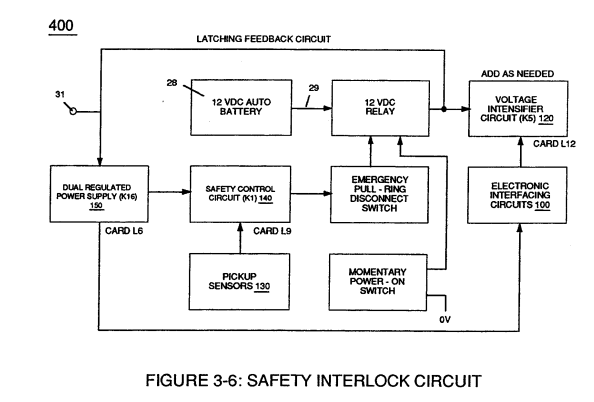
Variable voltage range (32a xxx 32n) from one (1) up to twelve (12) volts (regulating battery voltage) is applied across primary coil (26) of Voltage Intensifier Circuit (60) of Figure (3-21).
Energy Pumping Action 1×
-
energy transfer path (12)
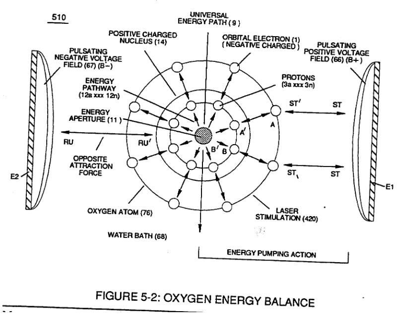
In this phase of application, opposite attraction force (BB') provides a energy transfer path (12) to each respective proton (3a xxx 3n) from energy aperture (11) which is centrally formed during proton grouping ... establishing nucleus (14) of Figure (5-2).
Appendix 3 1×
-
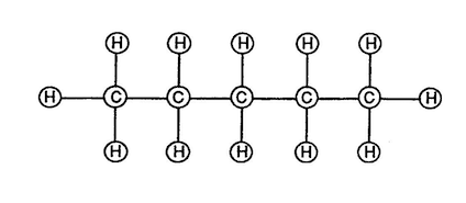
Natural Gas is composed of (5) carbon atoms and (12) hydrogen atoms to form a molecule of gas.